Adding TextDrawable as a PlaceHolder in Open Event Android App

The Open Event Android project has a fragment for showing speakers of the event. Each Speaker model has image-url which is used to fetch the image from server and load in the ImageView. In some cases it is possible that image-url is null or client is not able to fetch the image from the server because of the network problem. So in these cases showing Drawable which contains First letters of the first name and the last name along with a color background gives great UI and UX. In this post I explain how to add TextDrawable as a placeholder in the ImageView using TextDrawable library.

1. Add dependency

In order to use TextDrawable in your app add following dependencies in your app module’s build.gradle file.

dependencies {
	compile 'com.amulyakhare:com.amulyakhare.textdrawable:1.0.1'
}

2. Create static TextDrawable builder

Create static method in the Application class which returns the builder object for creating TextDrawables. We are creating static method so that the method can be used all over the App.

private static TextDrawable.IShapeBuilder textDrawableBuilder;

public static TextDrawable.IShapeBuilder getTextDrawableBuilder()
 {
        if (textDrawableBuilder == null) {
            textDrawableBuilder = TextDrawable.builder();
        }
        return textDrawableBuilder;
}

This method first checks if the builder object is null or not and then initialize it if null. Then it returns the builder object.

3.  Create and initialize TextDrawable object

Now create a TextDrawable object and initialize it using the builder object. The Builder has methods like buildRound(), buildRect() and buildRoundRect() for making drawable round, rectangle and rectangle with rounded corner respectively. Here we are using buildRect() to make the drawable rectangle.

TextDrawable drawable = OpenEventApp.getTextDrawableBuilder()
                    .buildRect(Utils.getNameLetters(name), ColorGenerator.MATERIAL.getColor(name));

The buildRect() method takes two arguments one is String text which will be used as a text in the drawable and second is int color which will be used as a background color of the drawable. Here ColorGenerator.MATERIAL returns material color for given string.

4.  Create getNameLetters()  method

The getNameLetters(String name) method should return the first letters of the first name and last name as String.

Example, if the name is “Shailesh Baldaniya” then it will return “SB”.

public static String getNameLetters(String name) {
        if (isEmpty(name))
            return "#";

        String[] strings = name.split(" ");
        StringBuilder nameLetters = new StringBuilder();
        for (String s : strings) {
            if (nameLetters.length() >= 2)
                return nameLetters.toString().toUpperCase();
            if (!isEmpty(s)) {
                nameLetters.append(s.trim().charAt(0));
            }
        }
        return nameLetters.toString().toUpperCase();
}

Here we are using split method to get the first name and last name from the name. The charAt(0) gives the first character of the string. If the name string is null then it will return “#”.   

5.  Use Drawable

Now after creating the TextDrawable object we need to load it as a placeholder in the ImageView for this we are using Picasso library.

Picasso.with(context)
        .load(image-url)
        .placeholder(drawable)
        .error(drawable)
        .into(speakerImage);

Here the placeholder() method displays drawable while the image is being loaded. The error() method displays drawable when the requested image could not be loaded when the device is offline. SpeakerImage is an ImageView in which we want to load the image.

Conclusion

TextDrawable is a great library for generating Drawable with text. It has also support for animations, font and shapes. To know more about TextDrawable follow the links given below.

Continue ReadingAdding TextDrawable as a PlaceHolder in Open Event Android App

Adding Voice Recognition in Description Dialog Box in Phimpme project

In this blog, I will explain how I added Voice Recognition in a dialog box to describe an image in Phimpme Android application. In Phimpme Android application we have an option to add a description for the image. Sometimes the description can be long. Adding Voice Recognition text to speech will ease the user’s experience to add a description for the image.

Adding appropriate Dialog Box

In order to take input from the user to prompt the Voice Recognition function, I have added an image button in the description dialog box. Since the description dialog box will only contain an EditText and a button will have used material design to make it look better and add caption on top of it.


<LinearLayout
   android:id="@+id/rl_description_dialog"
   android:layout_width="match_parent"
   android:layout_height="wrap_content"
   android:orientation="horizontal"
   android:padding="15dp">
   <EditText
       android:id="@+id/description_edittxt"
       android:layout_weight="1"
       android:layout_width="fill_parent"
       android:layout_height="wrap_content"
       android:padding="15dp"
       android:hint="@string/description_hint"
       android:textColorHint="@color/grey"
       android:layout_margin="20dp"
       android:gravity="top|left"
       android:inputType="text" />
   <ImageButton
       android:layout_width="@dimen/mic_image"
       android:layout_height="@dimen/mic_image"
       android:layout_alignRight="@+id/description_edittxt"
       app2:srcCompat="@drawable/ic_mic_black"
       android:layout_gravity="center"
       android:background="@color/transparent"
       android:paddingEnd="10dp"
       android:paddingTop="12dp"
       android:id="@+id/voice_input"/>
</LinearLayout>

Function to prompt dialog box

We have added a function to prompt the dialog box from anywhere in the application. getDescriptionDialog() function is used to prompt the description dialog box. getDescriptionDialog() returns EditText which can be further be used to manipulate the text in the EditText. Please follow the following steps to inflate description dialog box in the activity.

First,

In the getDescriptionDialog() function we will inflate the layout by using getLayoutInflater function. We will pass the layout id as an argument in the function.

public EditText getDescriptionDialog(final ThemedActivity activity, AlertDialog.Builder descriptionDialog){
final View DescriptiondDialogLayout = activity.getLayoutInflater().inflate(R.layout.dialog_description, null);

Second,

Get the TextView in the description dialog box.

final TextView DescriptionDialogTitle = (TextView) DescriptiondDialogLayout.findViewById(R.id.description_dialog_title);

Third,

Present the dialog using cardview to make use of the material design. Then take an instance of the EditText. This EditText can be further used to input text from the user either by text or Voice Recognition.

final CardView DescriptionDialogCard = (CardView) DescriptiondDialogLayout.findViewById(R.id.description_dialog_card);
EditText editxtDescription = (EditText) DescriptiondDialogLayout.findViewById(R.id.description_edittxt);

Fourth,

Set onClickListener when the user clicks the mic image icon. This onClicklistener will prompt the voice Recognition in the activity. We need to specify the language for the speech to text input. In the case of Phimpme its English so “en-US”. We have set the maximum results to 15.  

ImageButton VoiceRecognition = (ImageButton) DescriptiondDialogLayout.findViewById(R.id.voice_input);
VoiceRecognition.setOnClickListener(new View.OnClickListener() {
   @Override
   public void onClick(View v) {
       // This are the intents needed to start the Voice recognizer
       Intent i = new Intent(RecognizerIntent.ACTION_RECOGNIZE_SPEECH);
       i.putExtra(RecognizerIntent.EXTRA_LANGUAGE_MODEL, "en-US");
       i.putExtra(RecognizerIntent.EXTRA_MAX_RESULTS, 15); // number of maximum results..
       i.putExtra(RecognizerIntent.EXTRA_PROMPT, R.string.caption_speak);
       startActivityForResult(i, REQ_CODE_SPEECH_INPUT);

   }
});

Putting Text in the EditText

After Voice Recognition prompt ends the onActivityResult function checks to see if the data is received or not.

if (requestCode == REQ_CODE_SPEECH_INPUT && data!=null) {

We get the spoken text from intent data.getString() and store it in ArrayList. To store the received data in a string we need to get the first string from the ArrayList.

ArrayList<String> result = data
       .getStringArrayListExtra(RecognizerIntent.EXTRA_RESULTS);
voiceInput = result.get(0);

Setting the received data in the the EditText

editTextDescription.setText(voiceInput);

Conclusion

Using Voice recognition is a quick and simple way to add a long description on the image. It’s Speech to Text feature works without many mistakes and is useful in our Phimpme Android application.

Github

https://github.com/fossasia/phimpme-android

Resources

Tutorial for speech to Text: https://www.androidhive.info/2014/07/android-speech-to-text-tutorial/

To add description dialog box: https://developer.android.com/guide/topics/ui/dialogs.html

Continue ReadingAdding Voice Recognition in Description Dialog Box in Phimpme project

Google Authentication and sharing Image on Google Plus from Phimpme Android

In this blog, I will be explaining how I implemented Google Authentication and sharing an Image on GooglePlus from Phimpme Android application.

Adding Google Plus authentication in accounts activity in Phimpme Android

In accounts Activity, we added Google Plus option. This is done by adding “Googleplus” in accountName.  

public static String[] accountName = { "Facebook", "Twitter", "Drupal", "NextCloud", "Wordpress", "Pinterest", "Flickr", "Imgur", "Dropbox", "OwnCloud", "Googleplus"};

Add this to your Gradle Build. Please note that the version of Google:play-services in the grade should be same. In the case of Phimpme the version is 10.0.1, so all the services from Google should be 10.0.1.

compile 'com.google.android.gms:play-services-auth:10.0.1

In onCreate we need to make the object of the GoogleSignInOptions. This is required to call methods: requestEmail() and build.

GoogleSignInOptions gso = new GoogleSignInOptions.Builder(GoogleSignInOptions.DEFAULT_SIGN_IN)
       .requestEmail()
       .build();

Building GoogleApiClient with access to the Google Sign and the option specified by the gso.

mGoogleApiClient = new GoogleApiClient.Builder(this)
       .enableAutoManage(this , AccountActivity.this)
       .addApi(Auth.GOOGLE_SIGN_IN_API, gso)
       .build();

Signing in Google Authentication can take place through intent which calls logged in users on the phone. The user will choose an option to select the account he or she wants to authenticate the application.

private void signInGooglePlus() {
   Intent signInIntent = Auth.GoogleSignInApi.getSignInIntent(mGoogleApiClient);
   startActivityForResult(signInIntent, RC_SIGN_IN);
}

Adding Google Plus account in the Realm Database

HandleSignInResult() function is used to handle Sign in result. This result includes:

Storing the received data in the Realm Database. Showing the appropriate username in the Accounts activity and handling login failed.

Checking if login is successful or not

If the login is successful a Toast message will pop up to show the appropriate message.  

private void handleSignInResult(GoogleSignInResult result) {
   if (result.isSuccess())
       GoogleSignInAccount acct = result.getSignInAccount();//acct.getDisplayName()
       Toast.makeText(AccountActivity.this, R.string.success, Toast.LENGTH_SHORT).show();

Creating Object to store the details in Realm Database.

First, we need to begin realm transaction.Then add logged in username in the database.

To display the username we will create the function setUserName(acct.getDisplayName()). And then finally commit everything to Realm database.  

       realm.beginTransaction();
       account = realm.createObject(AccountDatabase.class,
       accountName[GOOGLEPLUS]);
       account.setUsername(acct.getDisplayName());
       realm.commitTransaction();
   }

Adding Google Plus option in Sharing Activity.

To add Google Plus option in the sharing Activity we first added Google Plus icon in the resource folder.

The Google Plus icon is SVG(scalable vector) format so that we can manipulate it to apply any colour and size.

<vector xmlns:android="http://schemas.android.com/apk/res/android"
   android:width="24dp"
   android:height="24dp"
   android:viewportHeight="32.0"
   android:viewportWidth="32.0">
   <path
       android:fillColor="#00000000"
       android:pathData="M16,16m-16,0a16,16 0,1 1,32 0a16,16 0,1 1,-32 0" />
   <path
       android:fillColor="#000000"
       android:pathData="M16.7,17.2c-0.4,-0.3 -1.3,-1.1 -1.3,-1.5c0,-0.5 0.2,-0.8 1,-1.4c0.8,-0.6 1.4,-1.5 1.4,-2.6c0,-1.2 -0.6,-2.5 -1.6,-2.9h1.6L18.8,8h-5c-2.2,0 -4.3,1.7 -4.3,3.6c0,2 1.5,3.6 3.8,3.6c0.2,0 0.3,0 0.5,0c-0.1,0.3 -0.3,0.6 -0.3,0.9c0,0.6 0.3,1 0.7,1.4c-0.3,0 -0.6,0 -0.9,0c-2.8,0 -4.9,1.8 -4.9,3.6c0,1.8 2.3,2.9 5.1,2.9c3.1,0 4.9,-1.8 4.9,-3.6C18.4,19 18,18.1 16.7,17.2zM14.1,14.7c-1.3,0 -2.5,-1.4 -2.7,-3.1c-0.2,-1.7 0.6,-3 1.9,-2.9c1.3,0 2.5,1.4 2.7,3.1C16.2,13.4 15.3,14.8 14.1,14.7zM13.6,23.2c-1.9,0 -3.3,-1.2 -3.3,-2.7c0,-1.4 1.7,-2.6 3.6,-2.6c0.4,0 0.9,0.1 1.2,0.2c1,0.7 1.8,1.1 2,1.9c0,0.2 0.1,0.3 0.1,0.5C17.2,22.1 16.2,23.2 13.6,23.2zM21.5,15v-2h-1v2h-2v1h2v2h1v-2h2v-1H21.5z" />
</vector>

Sharing Image on Google Plus from Sharing Activity

After creating the appropriate button, we need to send the image to Google Plus. We need to import the PlusShare files in the SharingActivity.

import com.google.android.gms.plus.PlusShare;

Share Image function

To share the image on Google Plus we have used PlusShare function which comes in Google Plus API. In the function shareToGoogle() we will send the message and the image on Google Plus.

To send the message: share.setText(“Provide the message you want to pass”) .

To send the Image:share.addStream(Uri of the Image to be sent).

private void shareToGoogle() {
   Uri uri = getImageUri(context);
   PlusShare.Builder share = new PlusShare.Builder(this);
   share.setText(caption);
   share.addStream(uri);
   share.setType(getResources().getString(R.string.image_type));
   startActivityForResult(share.getIntent(), REQ_SELECT_PHOTO);
}

Show appropriate message after uploading the image

After uploading the image on Google Plus there can be two possibilities:

  1. Image failed to upload
  2. Image uploaded successfully.

If the image uploaded image successfully an appropriate message is displayed in snackbar.

If the image upload fails an error message is displayed.

if (requestCode == REQ_SELECT_PHOTO) {
   if (responseCode == RESULT_OK) {
       Snackbar.make(parent, R.string.success_google, Snackbar.LENGTH_LONG).show();
       return;
   } else {
       Snackbar.make(parent, R.string.error_google, Snackbar.LENGTH_LONG).show();
       return;
   }
}

Conclusion

This is how we have implemented image share on Google Plus in Phimpme. Following this method, it will provide an easy way to upload an image on Google Plus without leaving or switching between the Phimpme application.

Github

https://github.com/fossasia/phimpme-android

Resources


Continue ReadingGoogle Authentication and sharing Image on Google Plus from Phimpme Android

Displaying an Animated Image in Splash Screen of Phimpme Android

A splash screen is the welcome page of the application. It gives the first impression of the application to the user. So, it is very important to make this page a better-looking one. In Phimpme Android, we had a normal page with a static image which is very common in all applications. So, in order to make it different from the most applications, we created an animation of the logo and added it to the splash screen.

As the splash screen is the first page/activity of the Phimpme Android application, most of the initialization functions are called in this activity. These initializations might take a little time giving us the time to display the logo animation.

Creating the animation of the Phimpme logo

For creating the animation of the Phimpme Android application’s logo, we used Adobe After Effects software. There are many free tools available on the web for creating the animation but due to the sophistic features present in After Effects, we used that software. We created the Phimpme Android application’s logo animation like any other normal video but with a lower frame rate. We used 12 FPS for the animation and it was fine as it was for a logo. Finally, we exported the animation as a transparent PNG formatted image sequence.

How to display the animation?

In Phimpme Android, we could’ve directly used the sequence of resultant images for displaying the animation. We could’ve done that by using a handler to change the image resource of an imageview. But this approach is very crude. So, we planned to create a GIF with the image sequence first and then display the GIF in the image view.

Creating a GIF from the image sequence

There are many tools on the web which create a GIF image from the given image sequence but most of the tools don’t support transparent images. This tool which we used to create the transparent GIF image supports both transparent and normal images. The frame rate and loop count can also be adjusted using this free tool. Below is the GIF image created using that tool.

Displaying the GIF in Phimpme

GIF image can be displayed in Phimpme Android application very easily using the famous Glide image caching and displaying library. But glide library doesn’t fulfill the need of the current scenario. Here, in Phimpme Android, we are displaying the GIF in the splash screen i.e. the next page should get displayed automatically. As we are showing an intro animation, the next activity/page should get opened only after the animation is completed. For achieving this we need a listener which triggers on the loop completion of the GIF image. Glide doesn’t provide any listener of this kind so we cannot Glide here.

There is a library named android-gif-drawable, which has the support for a GIF completion listener and many other methods. So, we used this for displaying the Phimpme Android application’s logo animation GIF image in the splash screen. When the GIF completed function gets triggered, we started the next activity if all the tasks which had to get completed in this activity itself are finished. Otherwise, we added a flag that the animation is done so that when the task gets completed, it just navigates to next page.

The way of the implementation described above is performed in Phimpme Android in the following manner.

First of all, we imported the library by adding it to the dependencies of build.gradle file.

compile 'pl.droidsonroids.gif:android-gif-drawable:1.2.7'

Then we added a normal imageview widget in the layout of the SplashScreen activity.

<ImageView
   android:id="@+id/imgLogo"
   android:layout_width="match_parent"
   android:layout_height="wrap_content"
   android:scaleType="fitCenter"
   android:layout_centerInParent="true"
   />

Finally, in the SplashScreen.java, we created a GifDrawable object using the GIF image of Phimpme Android logo animation, which we copied in the assets folder of the Phimpme application. We added a listener to the GifDrawble and added function calls inside that function. It is shown below.

GifDrawable gifDrawable = null;
try {
   gifDrawable = new GifDrawable( getAssets(), "splash_logo_anim.gif" );
} catch (IOException e) {
   e.printStackTrace();
}
if (gifDrawable != null) {
   gifDrawable.addAnimationListener(new AnimationListener() {
       @Override
       public void onAnimationCompleted(int loopNumber) {
           Log.d("splashscreen","Gif animation completed");
           if (can_be_finished && nextIntent != null){
               startActivity(nextIntent);
               finish();
           }else {
               can_be_finished = true;
           }
       }
   });
}
logoView.setImageDrawable(gifDrawable);

Resources:

Continue ReadingDisplaying an Animated Image in Splash Screen of Phimpme Android

Implement Wave Generation Functionality in The PSLab Android App

The PSLab Android App works as an Oscilloscope using the audio jack of Android device. The implementation for the scope using in-built mic is discussed in the post Using the Audio Jack to make an Oscilloscope in the PSLab Android App. Another application which can be implemented by hacking the audio jack is Wave Generation. We can generate different types of signals on the wires connected to the audio jack using the Android APIs that control the Audio Hardware. In this post, I will discuss about how we can generate wave by using the Android APIs for controlling the audio hardware.

Configuration of Audio Jack for Wave Generation

Simply cut open the wire of a cheap pair of earphones to gain control of its terminals and attach alligator pins by soldering or any other hack(jugaad) that you can think of. After you are done with the tinkering of the earphone jack, it should look something like shown in the image below.

Source: edn.com

If your earphones had mic, it would have an extra wire for mic input. In any general pair of earphones the wire configuration is almost the same as shown in the image below.

Source: flickr

Android APIs for Controlling Audio Hardware

AudioRecord and AudioTrack are the two classes in Android that manages recording and playback respectively. For Wave Generation application we only need AudioTrack class.

Creating an AudioTrack object: We need the following parameters to initialise an AudioTrack object.

STREAM TYPE: Type of stream like STREAM_SYSTEM, STREAM_MUSIC, STREAM_RING, etc. For wave generation purpose we are using stream music. Every stream has its own maximum and minimum volume level.

SAMPLING RATE: it is the rate at which source samples the audio signal.

BUFFER SIZE IN BYTES: total size in bytes of the internal buffer from where the audio data is read for playback.

MODES: There are two modes

  • MODE_STATIC: Audio data is transferred from Java to native layer only once before the audio starts playing.
  • MODE_STREAM: Audio data is streamed from Java to native layer as audio is being played.

getMinBufferSize() returns the estimated minimum buffer size required for an AudioTrack object to be created in the MODE_STREAM mode.

private int minTrackBufferSize;
private static final int SAMPLING_RATE = 44100;
minTrackBufferSize = AudioTrack.getMinBufferSize(SAMPLING_RATE, AudioFormat.CHANNEL_OUT_MONO, AudioFormat.ENCODING_PCM_16BIT);

audioTrack = new AudioTrack(
       AudioManager.STREAM_MUSIC,
       SAMPLING_RATE,
       AudioFormat.CHANNEL_OUT_MONO,
       AudioFormat.ENCODING_PCM_16BIT,
       minTrackBufferSize,
       AudioTrack.MODE_STREAM);

Function createBuffer() creates the audio buffer that is played using the audio track object i.e audio track object would write this buffer on playback stream. Function below fills random values in the buffer due to which a random signal is generated. If we want to generate some specific wave like Square Wave, Sine Wave, Triangular Wave, we have to fill the buffer accordingly.

public short[] createBuffer(int frequency) {
   // generating a random buffer for now
   short[] buffer = new short[minTrackBufferSize];
   for (int i = 0; i < minTrackBufferSize; i++) {
       buffer[i] = (short) (random.nextInt(32767) + (-32768));
   }
   return buffer;
}

We created a write() method and passed the audio buffer created in above step as an argument to the method. This method writes audio buffer into audio stream for playback.

public void write(short[] buffer) {
   /* write buffer to audioTrack */
   audioTrack.write(buffer, 0, buffer.length);
}

Amplitude of the signal can be controlled by changing the volume level of the stream on which the buffer is being played. As we are playing the audio in music stream, so STREAM_MUSIC is passed as a parameter to the setStreamVolume() method.

value: value is amplitude level of the stream. Every stream has its different amplitude levels. getStreamMaxVolume(STREAM_TYPE) method is used to find the maximum valid amplitude level of any stream.
flag: this stackoverflow post explain all the flags of the AudioManager class.

AudioManager audioManager = (AudioManager)getSystemService(Context.AUDIO_SERVICE); audioManager.setStreamVolume(AudioManager.STREAM_MUSIC, value, flag);

Roadmap

We are working on implementing methods to fill audio buffer with specific values such that waves like Sinusoidal wave, Square Wave, Sawtooth Wave can be generated during the playback of the buffer using the AudioTrack object.

Resources

Continue ReadingImplement Wave Generation Functionality in The PSLab Android App

Data Access Layer in Open Event Organizer Android App

Open Event Organizer is an Android App for Organizers and Entry Managers. Its core feature is scanning a QR Code to validate Attendee Check In. Other features of the App are to display an overview of sales and tickets management. The App maintains a local database and syncs it with the Open Event API Server. The Data Access Layer in the App is designed such that the data is fetched from the server or taken from the local database according to the user’s need. For example, simply showing the event sales overview to the user will fetch the data from the locally saved database. But when the user wants to see the latest data then the App need to fetch the data from the server to show it to the user and also update the locally saved data for future reference. I will be talking about the data access layer in the Open Event Organizer App in this blog.

The App uses RxJava to perform all the background tasks. So all the data access methods in the app return the Observables which is then subscribed in the presenter to get the data items. So according to the data request, the App has to create the Observable which will either load the data from the locally saved database or fetch the data from the API server. For this, the App has AbstractObservableBuilder class. This class gets to decide which Observable to return on a data request.

Relevant Code:

final class AbstractObservableBuilder<T> {
   ...
   ...
   @NonNull
   private Callable<Observable<T>> getReloadCallable() {
       return () -> {
           if (reload)
               return Observable.empty();
           else
               return diskObservable
                   .doOnNext(item -> Timber.d("Loaded %s From Disk on Thread %s",
                       item.getClass(), Thread.currentThread().getName()));
       };
   }

   @NonNull
   private Observable<T> getConnectionObservable() {
       if (utilModel.isConnected())
           return networkObservable
               .doOnNext(item -> Timber.d("Loaded %s From Network on Thread %s",
                   item.getClass(), Thread.currentThread().getName()));
       else
           return Observable.error(new Throwable(Constants.NO_NETWORK));
   }

   @NonNull
   private <V> ObservableTransformer<V, V> applySchedulers() {
       return observable -> observable
           .subscribeOn(Schedulers.io())
           .observeOn(AndroidSchedulers.mainThread());
   }

   @NonNull
   public Observable<T> build() {
       if (diskObservable == null || networkObservable == null)
           throw new IllegalStateException("Network or Disk observable not provided");

       return Observable
               .defer(getReloadCallable())
               .switchIfEmpty(getConnectionObservable())
               .compose(applySchedulers());
   }
}


The class is used to build the Abstract Observable which contains both types of Observables, making data request to the API server and the locally saved database. Take a look at the method build. Method getReloadCallable provides an observable which will be the default one to be subscribed which is a disk observable which means data is fetched from the locally saved database. The method checks parameter reload which if true suggests to make the data request to the API server or else to the locally saved database. If the reload is false which means data can be fetched from the locally saved database, getReloadCallable returns the disk observable and the data will be fetched from the locally saved database. If the reload is true which means data request must be made to the API server, then the method returns an empty observable.

The method getConnectionObservable returns a network observable which makes the data request to the API server. In the method build, switchIfEmpty operator is applied on the default observable which is empty if reload is true, and the network observable is passed to it. So when reload is true, network observable is subscribed and when it is false disk observable is subscribed. For example of usage of this class to make a events data request is:

public Observable<Event> getEvents(boolean reload) {
   Observable<Event> diskObservable = Observable.defer(() ->
       databaseRepository.getAllItems(Event.class)
   );

   Observable<Event> networkObservable = Observable.defer(() ->
       eventService.getEvents(JWTUtils.getIdentity(getAuthorization()))
           ...
           ...

   return new AbstractObservableBuilder<Event>(utilModel)
       .reload(reload)
       .withDiskObservable(diskObservable)
       .withNetworkObservable(networkObservable)
       .build();
}


So according to the boolean parameter reload, a correct observable is subscribed to complete the data request.

Links:
1. Documentation about the Operators in ReactiveX
2. Information about the Data Access Layer on Wikipedia

Continue ReadingData Access Layer in Open Event Organizer Android App

Basics behind BJT and FET experiments in PSLab

A high school student in his curriculum; will come across certain electronics and electrical experiments. One of them related to semiconductor devices such as Bipolar Junction Transistors (BJTs) and Field Effect Transistors (FETs). PSLab device is capable of function as a waveform generator, voltage and current source, oscilloscope and multimeter. Using these functionalities one can design an experiment. This blog post brings out the basics one should know about the experiment and the PSLab device to program an experiment in the saved experiments section.

Channels and Sources in the PSLab Device

The PSLab device has three pins dedicated to function as programmable voltage sources (PVS) and one pin for programmable current source (PCS).

Programmable Voltage Sources can generate voltages as follows;

  • PV1 →  -5V ~ +5V
  • PV2 → -3.3V ~ +3.3V
  • PV3 → 0 ~ +3.3V

Programmable Current Source (PCS) can generate current as follows;

  • PCS → 0 ~ 3.3mA

The device has 4 channel oscilloscope out of those CH1, CH2 and CH3 pins are useful in experiments of the current context type.

About BJTs and FETs

Every semiconductor device is made of Silicon(Si). Some are made of Germanium(Ge) but they are not widely used. Silicon material has a potential barrier of 0.7 V among P type and N type sections of a semiconductor device. This voltage value is really important in an experiment as in some practicals such as “BJT Amplifier”, there is no use of a voltage value setting below this value. So the experiment needs to be programmed to have 0.7V as the minimum voltage for Base terminal.

Basic BJT experiments

BJTs have three pins. Collector, Emitter and Base. Current to the Base pin will control the flow of electrons from Emitter to Collector creating a voltage difference between Collector and Emitter pins. This scenario can be taken down to three types as;

  • Input Characteristics → Relationship between Emitter current to VBE(Base to Emitter)
  • Output Characteristics → Relationship between IC(Collector) to VCB(Collector to Base)
  • Transfer Characteristics → Relationship between IC(Collector) to IE(Emitter)

Input Characteristics

Output Characteristics

Transfer Characteristics


Basic FET experiments

FETs have three pins. Drain, Source and Gate. Voltage to Gate terminal will control the electron flow from either direction from or to Source and Drain. This scenario results in two types of experiments;

  • Output Characteristics → Drain current to Drain to Source voltage difference
  • Transfer Characteristics → Gate to Source voltage to Drain current
Output Characteristics Transfer Characteristics

Using existing methods in PSLab android repository

Current implementation of the android application consists of all the methods required to read voltages and currents from the relevant pins and fetch waveforms from the channel pins and output voltages from PVS pins.

ScienceLab.java class – This class implements all the methods required for any kind of an experiment. The methods that will be useful in designing BJT and FET related experiments are;

Set Voltages

public void setPV1(float value);

public void setPV2(float value);

public void setPV3(float value);

Set Currents

public void setPCS(float value);

Read Voltages

public double getVoltage(String channelName, Integer sample);

Read Currents

To read current there is no direct way implemented. The current flow between two nodes can be calculated using the PVS pin value and the voltage value read from the channel pins. It uses Ohm’s law to calculate the value using the known resistance between two nodes.

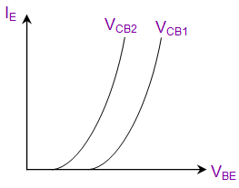
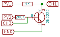
In the following schematic; the collector current can be calculated using known PV1 value and the measured CH1 value as follows;

IC = (PV1 – CH1) / 1000

This is how it is actually implemented in the existing experiments.

If one needs to implement a new experiment of any kind, these are the basics need to know. There can be so many new experiments implemented using these basics. Some of them could be;

  • Effect of Temperature coefficient in Collector current
  • The influence in β factor in Collector current

Resources:

Continue ReadingBasics behind BJT and FET experiments in PSLab
Read more about the article Automatic handling of view/data interactions in Open Event Orga App
Abstract 3d white geometric background. White seamless texture with shadow. Simple clean white background texture. 3D Vector interior wall panel pattern.

Automatic handling of view/data interactions in Open Event Orga App

During the development of Open Event Orga Application (Github Repo), we have strived to minimize duplicate code wherever possible and make the wrappers and containers around data and views intelligent and generic. When it comes to loading the data into views, there are several common interactions and behaviours that need to be replicated in each controller (or presenter in case of MVP architecture as used in our project). These interactions involve common ceremony around data loading and setting patterns and should be considered as boilerplate code. Let’s look at some of the common interactions on views:

Loading Data

While loading data, there are 3 scenarios to be considered:

  • Data loading succeeded – Pass the data to view
  • Data loading failed – Show appropriate error message
  • Show progress bar on starting of the data loading and hide when completed

If instead of loading a single object, we load a list of them, then the view may be emptiable, meaning you’ll have to show the empty view if there are no items.

Additionally, there may be a success message too, and if we are refreshing the data, there will be a refresh complete message as well.

These use cases present in each of the presenter cause a lot of duplication and can be easily handled by using Transformers from RxJava to compose common scenarios on views. Let’s see how we achieved it.

Generify the Views

The first step in reducing repetition in code is to use Generic classes. And as the views used in Presenters can be any class such as Activity or Fragment, we need to create some interfaces which will be implemented by these classes so that the functionality can be implementation agnostic. We broke these scenarios into common uses and created disjoint interfaces such that there is little to no dependency between each one of these contracts. This ensures that they can be extended to more contracts in future and can be used in any View without the need to break them down further. When designing contracts, we should always try to achieve fundamental blocks of building an API rather than making a big complete contract to be filled by classes. The latter pattern makes it hard for this contract to be generally used in all classes as people will refrain from implementing all its methods for a small functionality and just write their own function for it. If there is a need for a class to make use of a huge contract, we can still break it into components and require their composition using Java Generics, which we have done in our Transformers.

First, let’s see our contracts. Remember that the names of these Contracts are opinionated and up to the developer. There is no rule in naming interfaces, although adjectives are preferred as they clearly denote that it is an interface describing a particular behavior and not a concrete class:

Emptiable

A view which contains a list of items and thus can be empty

public interface Emptiable<T> {
   void showResults(List<T> items);
   void showEmptyView(boolean show);
}

Erroneous

A view that can show an error message on failure of loading data

public interface Erroneous {
   void showError(String error);
}

ItemResult

A view that contains a single object as data

public interface ItemResult<T> {
   void showResult(T item);
}

Progressive

A view that can show and hide a progress bar while loading data

public interface Progressive {
   void showProgress(boolean show);
}

Note that even though Progressive view can only be the one which is either ItemResult or Emptiable as they are the ones containing any data, but we have decoupled it, making it possible for a view to load data without progress or show progress for any other implementation other than loading data.

Refreshable

A view that can be refreshed and show the refresh complete message

public interface Refreshable {
   void onRefreshComplete();
}

There should also be a method for refresh failure, but the app is under development and will be added soon

Successful

A view that can show a success message

public interface Successful {
   void onSuccess(String message);
}

Implementation

Now, we will implement the Observable Transformers for these contracts

Erroneous

public static <T, V extends Erroneous> ObservableTransformer<T, T> erroneous(V view) {
   return observable ->  observable
             .doOnError(throwable -> view.showError(throwable.getMessage()));
}

We simply call showError on a view implementing Erroneous on the call of doOnError of the Observable

Progressive

private static <T, V extends Progressive> ObservableTransformer<T, T> progressive(V view) {
   return observable -> observable
           .doOnSubscribe(disposable -> view.showProgress(true))
           .doFinally(() -> view.showProgress(false));
}

Here we show the progress when the observable is subscribed and finally, we hide it whether it succeeded or failed

ItemResult

public static <T, V extends ItemResult<T>> ObservableTransformer<T, T> result(V view) {
   return observable -> observable.doOnNext(view::showResult);
}

We call showResult on call of onNext


Refreshable

private static <T, V extends Refreshable> ObservableTransformer<T, T> refreshable(V view, boolean forceReload) {
   return observable ->
       observable.doFinally(() -> {
           if (forceReload) view.onRefreshComplete();
       });
}

As we only refresh a view if it is a forceReload, so we check it before calling onRefreshComplete


Emptiable

public static <T, V extends Emptiable<T>> SingleTransformer<List<T>, List<T>> emptiable(V view, List<T> items) {
   return observable -> observable
       .doOnSubscribe(disposable -> view.showEmptyView(false))
       .doOnSuccess(list -> {
           items.clear();
           items.addAll(list);
           view.showResults(items);
       })
       .doFinally(() -> view.showEmptyView(items.isEmpty()));
}

Here we hide the empty view on start of the loading of data and finally we show it if the items are empty. Also, since we keep only one copy of a final list variable which is also used in view along with the presenter, we clear and add all items in that variable and call showResults on the view

Bonus: You can also merge the functions for composite usage as mentioned above like this

public static <T, V extends Progressive & Erroneous> ObservableTransformer<T, T> progressiveErroneous(V view) {
   return observable -> observable
       .compose(progressive(view))
       .compose(erroneous(view));
}

public static <T, V extends Progressive & Erroneous & ItemResult<T>> ObservableTransformer<T, T> progressiveErroneousResult(V view) {
   return observable -> observable
       .compose(progressiveErroneous(view))
       .compose(result(view));
}

Usage

Finally we use the above transformers

eventsDataRepository
   .getEvents(forceReload)
   .compose(dispose(getDisposable()))
   .compose(progressiveErroneousRefresh(getView(), forceReload))
   .toSortedList()
   .compose(emptiable(getView(), events))
   .subscribe(Logger::logSuccess, Logger::logError);

To give you an idea of what we have accomplished here, this is how we did the same before adding transformers

eventsView.showProgressBar(true);
eventsView.showEmptyView(false);

getDisposable().add(eventsDataRepository
   .getEvents(forceReload)
   .toSortedList()
   .subscribeOn(Schedulers.computation())
   .subscribe(events -> {
       if(eventsView == null)
           return;
       eventsView.showEvents(events);
       isListEmpty = events.size() == 0;
       hideProgress(forceReload);
   }, throwable -> {
       if(eventsView == null)
           return;

       eventsView.showEventError(throwable.getMessage());
       hideProgress(forceReload);
   }));

Sure looks ugly as compared to the current solution.

Note that if you don’t provide the error handler in subscribe method of the observable, it will throw an onErrorNotImplemented exception even if you have added a doOnError side effect

Here are some resources related to RxJava Transformers:

Continue ReadingAutomatic handling of view/data interactions in Open Event Orga App

Providing Support for Performing Rectifier Experiments in PSLab Android

PSLab can be used to perform Half and Full Wave Rectifier Experiments. A rectifier is an electrical device that converts alternating current (AC), which periodically reverses direction, to direct current (DC), which flows in only one direction. Half wave rectifiers clip out the negative part of the input waveform. The rectified signal can be further filtered with a capacitor in order to obtain a low ripple DC voltage. Only a diode is needed to clip out the negative part of the input signal. Full wave rectifiers combine the positive halves of 180 degrees out of phase input waveforms such as those output from AC transformers with a center tap. The rectified signal can be further filtered with a capacitor in order to obtain a low ripple DC voltage. Two diodes are used to clip out the negative parts of both inputs and combine them into a single output which is always in the positive region.

In order to support Half Wave Rectifier Experiments in PSLab, we used Oscilloscope Activity. For Half Rectifier Experiment we require to generate a sine wave from W1 channel and read signals from CH1 and CH2.

To implement this we first need to inform the Oscilloscope Activity whether Half Wave Rectifier Experiment needs to be performed or not. For this, we used putExtra and getExtra methods.

  Bundle extras = getIntent().getExtras();
  if ("Half Rectifier".equals(extras.getString("who"))) {
          isHalfWaveRectifierExperiment = true;        
 }

Then we programmatically change the layout. The side panel is made disappear and the graph and lower panel of the Oscilloscope expands horizontally.

if (isHalfWaveRectifierExperiment) {
            linearLayout.setVisibility(View.INVISIBLE);
            RelativeLayout.LayoutParams lineChartParams = (RelativeLayout.LayoutParams) mChartLayout.getLayoutParams();
            lineChartParams.height = height * 5 / 6;
            lineChartParams.width = width;
            RelativeLayout.LayoutParams frameLayoutParams = (RelativeLayout.LayoutParams) frameLayout.getLayoutParams();
            frameLayoutParams.height = height / 6;
            frameLayoutParams.width = width;
        }

The fragment for lower panel is replaced by the fragment designed for Half Wave Rectifier

halfwaveRectifierFragment = new HalfwaveRectifierFragment();
 
if (isHalfWaveRectifierExperiment) {
addFragment(R.id.layout_dock_os2, halfwaveRectifierFragment, "HalfWaveFragment");
 }

We get the following layout, ready to perform halfwave rectifier experiment.

For making the graph functional, capturing signals from CH1 and CH2 is required. For this, we reused CaptureTwo AsyncTask in such a way that it captures signals from CH1 and CH2 channels where CH1 is the input signal and CH2 is the output signal.

if (scienceLab.isConnected() && isHalfWaveRectifierExperiment) {
   captureTask2 = new CaptureTaskTwo();
   captureTask2.execute("CH1");
   synchronized (lock) {
       try {
           lock.wait();
       } catch (InterruptedException e) {
           e.printStackTrace();
       }
   }
}


By following the above steps we reused Oscilloscope Activity to perform Rectifier Experiments.

Resources

Continue ReadingProviding Support for Performing Rectifier Experiments in PSLab Android

Electronics Experiments with PSLab

Numerous college level electronics experiments can be performed using Pocket Science Lab (PSLab). The Android app and the Desktop app have all the essential features needed to perform these experiments and both these apps have quite a large number of experiments built-in. Some of the common experiments involve the use of BJT (Bipolar Junction Transistor), Zener Diode, FET (Field Effect Transistor), Op-Amp ( Operational Amplifier) etc. This blog walks through the details of performing some experiments using the above commonly used elements.  

The materials required for all the experiments are minimal and includes a few things like PSLab hardware device, components like Diodes, Transistors, Op-Amps etc., connecting wires/jumpers and secondary components like resistors, capacitors etc. Most of these elements would be a part of the PSLab Accessory Kit.

It is recommended to read this blog here, go through the resources mentioned at the end and also get acquainted with construction of circuits before advancing with the experiments mentioned in this blog.

Half Wave and Full Wave Rectifiers

The Bipolar Junction Transistor (BJT) can be used as a rectifier. Rectifiers are needed in circuits to obtain a nearly constant and stable output voltage and prevent any ripples in the circuit. The rectifier can be half wave or full wave depending on whether it rectifies one or both cycles of Alternating Voltage.

The circuit for the Half and Full Wave rectifier is given as follows:

  • Construct the above circuits on a breadboard.
  • For the half wave rectifier, connect the terminals of CH1 and GND of PSLab on the input side and the terminals of CH2 and GND on the output side.
  • The terminals of W1 and GND are also connected on the input side and they are used to generate a sine wave.
  • Use the PSLab Desktop App and open the Waveform Generator in Control. Set the wave type of W1 to Sine and set the frequency at 100 Hz and magnitude to 10mV. Then go ahead and open the Oscilloscope.
  • CH1 would display the input waveform and CH2 will display the output waveform and the plots can be observed.
  • The plot obtained will have rectification in only half of the cycle. In order to obtain rectification in the complete cycle, the full wave rectifier is needed.
  • For the full wave rectifier, the procedure is the same but an additional diode is used. Use an additional channel CH3 to plot the extra input.

  • The plot obtained from the above steps would still have ripples and so a capacitor is placed in parallel to cancel this effect.
  • Place a 100uF/330uF capacitor in parallel to the resistor RL and an additional 1 ohm resistor in the circuit.

BJT Inverter

  • Transistor has a lot of functions. The most common of them is its use as an amplifier. However, transistor can be used as a switch in a circuit i.e. as an inverter.
  • The circuit for this experiment is shown below. For this experiment, it is recommended to use an external 5V DC supply like a battery. Connect the transistor and the diode initially and then connect the resistors accordingly. (Connect the terminals of diode and transistor carefully else they will be damaged).
  • When the circuit is constructed completely, connect CH1 to Vi and CH2 to Vo. Vi and Vo are input and outputs respectively and are marked in the figure.
  • The terminals of W1 and GND are also connected on the input side and they are used to generate a sine wave.
  • Use the PSLab Desktop App and open the Waveform Generator in Control. Set the wave type of W1 to Sine and set the frequency at 200 Hz and magnitude to 10mV.
  • Then go ahead and open the Oscilloscope. Use the X-Y mode of the oscilloscope to obtain the plot between Vi and Vo which should look like the graph shown below.

Common Mode Gain and Differential Mode Gain in Op-Amps

Gain of any amplifier can be calculated by calculating the ratio of the output and input voltage. On plotting the graph in X-Y mode, a Vo vs Vi graph is obtained. The slope of that graph gives us the gain at any particular input voltage.

  • For finding the Differential Mode gain of an Op-Amp, construct the circuit as shown below.
  • When the circuit is constructed completely, connect CH1 to Vi and CH2 to Vo. Vi and Vo are input and outputs respectively and are marked in the figure. The terminals of W1 and GND are also connected on the input side and they are used to generate a sine wave.
  • The power supply provided to the Op-Amp are set to + 12V. (If faced with any confusion, please refer to the resources mentioned at the end of the blog to learn more about Op-Amps before proceeding ahead.)
  • Use the PSLab Desktop App and open the Waveform Generator in Control. Set the wave type of W1 to Sine and set the frequency at 1000 Hz and magnitude to 0.5V. Then go ahead and open the Oscilloscope. Use the X-Y mode of the oscilloscope to obtain the plot between Vi and Vo.
  • For finding the Common Mode gain of the Op-Amp, remove the waveform generator input i.e W1 from R3 and attach it to R2. The rest of the steps remain the same.

Schmitt Trigger

In electronics, a Schmitt trigger is a comparator circuit with hysteresis implemented by applying positive feedback to the noninverting input of a comparator or differential amplifier. It is an active circuit which converts an analog input signal to a digital output signal.

  • Construct the circuit as shown below. Although the diagram shows a variable resistor be used, a constant value resistor would also work fine.
  • When the circuit is constructed completely, connect CH1 to Vi and CH2 to Vo. Vi and Vo are input and outputs respectively and are marked in the figure. The terminals of W1 and GND are also connected on the input side and they are used to generate a sine wave.
  • The power supply provided to the Op-Amp are set to + 12V. (If faced with any confusion, please refer to the resources mentioned at the end of the blog to learn more about Op-Amps before proceeding ahead. If done incorrectly, Op-Amps will be damaged)
  • Use the PSLab Desktop App and open the Waveform Generator in Control. Set the wave type of W1 to Sine and set the frequency at 1000 Hz and magnitude to 0.5V. Then go ahead and open the Oscilloscope. Use the X-Y mode of the oscilloscope to obtain the plot between Vi and Vo which should look like the graph shown below.

Resources:

  1. Read more about Half wave and Full wave rectifier and their applications – https://en.wikipedia.org/wiki/Rectifier
  2. Read more about the Bipolar Junction Transistor and its use as a switch – http://www.electronicshub.org/transistor-as-switch/
  3. Understand the common mode and differential mode of Op-Amp – https://www.allaboutcircuits.com/video-lectures/op-amps-common-differential/
  4. Find more about Schmitt Trigger and its uses – https://en.wikipedia.org/wiki/Schmitt_trigger
Continue ReadingElectronics Experiments with PSLab