Capturing Position Data with PSLab Android App

PSLab Android app by FOSSASIA can be used to visualize different waveforms, signal levels and patterns. Many of them involve logging data from different instruments. These data sets can be unique and the user might want them to be specific to a location or a time. To facilitate this feature, PSLab Android app offers a feature to save user’s current location along with the data points.

This implementation can be done in two ways. One is to use Google Maps APIs and the other one is to use LocationManager classes provided by Android itself. The first one is more on to proprietary libraries and it will give errors when used in an open source publishing platform like Fdroid as they require all the libraries used in an app to be open. So we have to go with the latter, using LocationManager classes.

As first step, we will have to request permission from the user to allow the app access his current location. This can be easily done by adding a permission tag in the Manifest.xml file.

<uses-permission android:name="android.permission.ACCESS_FINE_LOCATION" />


Since we are not using Google Maps APIs, capturing the current location will take a little while and that can be considered as the only downfall of using this method. We have to constantly check for a location change to capture the data related to current location. This can be easily done by attaching a LocationListener as it will do the very thing for us.

private LocationListener locationListener = new LocationListener() {
   @Override
   public void onLocationChanged(Location location) {
       locationAvailable = true;
   }

   @Override
   public void onStatusChanged(String s, int i, Bundle bundle) {/**/}

   @Override
   public void onProviderEnabled(String s) {/**/}

   @Override
   public void onProviderDisabled(String s) {
       // TODO: Handle GPS turned on/off situations
   }
};


In case if the user has turned off GPS in his device, this method wouldn’t work. We will have to request him to turn the feature on using a simple dialog box or a bottom sheet dialog.

We can also customize how frequent the locationlistener should check for a location using another class named LocationManager. This class can be instantiated as follows:

locationManager = (LocationManager) getSystemService(Context.LOCATION_SERVICE);


Then we can easily set the time interval using requestLocationUpdates method. Here I have requested location updates in every one second. That is a quite reasonable rate.

locationManager.requestLocationUpdates(provider, 1000, 1, locationListener);


Once we have set all this up, we can capture the current location assuming that the user has turned on the GPS option from his device settings and the LocationManager class has a new location as we checked earlier.

if (locationAvailable) {
   Location location = locationManager.getLastKnownLocation(LocationManager.GPS_PROVIDER);
}


Each location will contain details related to its position such as latitudes and longitudes. We can log these data using the CSVLogger class implementation in PSLab Android app and let user have this option while doing his experiments.

Reference:

  1. An open source implementation : https://github.com/borneq/HereGPSLocation/blob/master/app/src/main/java/com/borneq/heregpslocation/MainActivity.java

Google Maps: https://developers.google.com/maps/documentation/android-sdk/intro

Continue ReadingCapturing Position Data with PSLab Android App

Performing Custom Experiments with PSLab

PSLab has the capability to perform a variety of experiments. The PSLab Android App and the PSLab Desktop App have built-in support for about 70 experiments. The experiments range from variety of trivial ones which are for school level to complicated ones which are meant for college students. However, it is nearly impossible to support a vast variety of experiments that can be performed using simple electronic circuits.

So, the blog intends to show how PSLab can be efficiently used for performing experiments which are otherwise not a part of the built-in experiments of PSLab. PSLab might have some limitations on its hardware, however in almost all types of experiments, it proves to be good enough.

  • Identifying the requirements for experiments

    • The user needs to identify the tools which are necessary for analysing the circuit in a given experiment. Oscilloscope would be essential for most experiments. The voltage & current sources might be useful if the circuit requires DC sources and similarly, the waveform generator would be essential if AC sources are needed. If the circuit involves the use and analysis of data of sensor, the sensor analysis tools might prove to be essential.
    • The circuit diagram of any given experiment gives a good idea of the requirements. In case, if the requirements are not satisfied due to the limitations of PSLab, then the user can try out alternate external features.
  • Using the features of PSLab

  • Using the oscilloscope
    • Oscilloscope can be used to visualise the voltage. The PSLab board has 3 channels marked CH1, CH2 and CH3. When connected to any point in the circuit, the voltages are displayed in the oscilloscope with respect to the corresponding channels.
    • The MIC channel can be if the input is taken from a microphone. It is necessary to connect the GND of the channels to the common ground of the circuit otherwise some unnecessary voltage might be added to the channels.

  • Using the voltage/current source
    • The voltage and current sources on board can be used for requirements within the range of +5V. The sources are named PV1, PV2, PV3 and PCS with V1, V2 and V3 standing for voltage sources and CS for current source. Each of the sources have their own dedicated ranges.
    • While using the sources, keep in mind that the power drawn from the PSLab board should be quite less than the power drawn by the board from the USB bus.
      • USB 3.0 – 4.5W roughly
      • USB 2.0 – 2.5W roughly
      • Micro USB (in phones) – 2W roughly
    • PSLab board draws a current of 140 mA when no other components are connected. So, it is advisable to limit the current drawn to less than 200 mA to ensure the safety of the device.
    • It is better to do a rough calculation of the power requirements in mind before utilising the sources otherwise attempting to draw excess power will damage the device.

  • Using the Waveform Generator
    • The waveform generator in PSLab is limited to 5 – 5000 Hz. This range is usually sufficient for most experiments. If the requirements are beyond this range, it is better to use an external function generator.
    • Both sine and square waves can be produced using the device. In addition, there is a feature to set the duty cycle in case of square waves.
  • Sensor Quick View and Sensor Data Logger
    • PSLab comes with the built in support for several plug and play sensors. The support for more sensors will be added in the future. If an experiment requires real time visualisation of sensor data, the Sensor Quick View option can be used whereas for recording the data for sensors for a period of time, the Sensor Data Logger can be used.
  • Analysing the Experiment

    • The oscilloscope is the most common tool for circuit analysis. The oscilloscope can sample data at very high frequencies (~250 kHz). The waveform at any point can be observed by connecting the channels of the oscilloscope in the manner mentioned above.
    • The oscilloscope has some features which will be essential like Trigger to stabilise the waveforms, XY Plot to plot characteristics graph of some devices, Fourier Transform of the Waveforms etc. The tools mentioned here are simple but highly useful.
    • For analysing the sensor data, the Sensor Quick View can be paused at any instant to get the data at any instant. Also, the logged data in Sensor Data Logger can be exported as a TXT/CSV file to keep a record of the data.
  • Additional Insight

    • The PSLab desktop app comes with the built-in support for the ipython console.
    • The desired quantities like voltages, currents, resistance, capacitance etc. can also be measured by using simple python commands through the ipython console.
    • A simple python script can be written to satisfy all the data requirements for the experiment. An example for the same is shown below.

This is script to produce two sine waves of 1 kHz and capturing & plotting the data.

from pylab import *
from PSL import sciencelab
I=sciencelab.connect()
I.set_gain('CH1', 2) # set input CH1 to +/-4V range
I.set_gain('CH2', 3) # set input CH2 to +/-4V range
I.set_sine1(1000) # generate 1kHz sine wave on output W1
I.set_sine2(1000) # generate 1kHz sine wave on output W2
#Connect W1 to CH1, and W2 to CH2. W1 can be attenuated using the manual amplitude knob on the PSlab
x,y1,y2 = I.capture2(1600,1.75,'CH1') 
plot(x,y1) #Plot of analog input CH1
plot(x,y2) #plot of analog input CH2
show()


References

Continue ReadingPerforming Custom Experiments with PSLab

Performing Diode Clipping and Clamping Experiment in PSLab Android

We can perform experiments like diode clipping and clamping using PSLab Android. A circuit which removes the peak of a waveform is known as a clipper. Diode clipper cuts off the top half or lower half or both top and lower half of the input signal. 

Different types of clipping circuits listed below

Different Clipping Experiments

A clamper circuit adds the positive dc component to the input signal to push it to the positive side. Similarly, a clamper circuit adds the negative dc component to the input signal to push it to the negative side. It basically shifts the input signal without changing the shape of the signal.

Different Clamping Experiments

Apparatus

Diode, Resistance, Capacitor (only for diode clamping), Breadboard, Wires and PSLab

Adding Diode Clipping Experiment support in PSLab Android App

To support Diode Clipping Experiment we require generating a sine wave and a dc component. This can be done using W1 and PV1 pins in PSLab device. Both input and output signals can be read using CH1 and CH2. So, when the Diode Clipping Experiment needs to be performed the following code needs to be implemented

scienceLab.setSine1(5000);
scienceLab.setPV1(//progress of the seekbar);

The signals are recorded using Oscilloscope Activity.

Adding Diode Clamping Experiment support in PSLab Android App

Diode Clamping Experiment was implemented similarly to Diode Clipping Experiment. The following are the screenshots of the experiment.     

The following is a glimpse of Diode Clamping Experiment performed using PSLab device using PSLab Android App.

Resources

  1. Read more about Clipper Circuits –
  2. Read more information about Clamping Circuits –
Continue ReadingPerforming Diode Clipping and Clamping Experiment in PSLab Android

The Pocket Science Lab: Who Needs it, and Why

Science and technology share a symbiotic relationship. The degree of success of experimentation is largely dependent on the accuracy and flexibility of instrumentation tools at the disposal of the scientist, and the subsequent findings in fundamental sciences drive innovation in technology itself. In addition to this, knowledge must be free as in freedom. That is, all information towards constructing such tools and using them must be freely accessible for the next generation of citizen scientists. A common platform towards sharing results can also be considered in the path to building a better open knowledge network.

But before we get to scientists, we need to consider the talent pool in the student community that gave rise to successful scientists, and the potential talent pool that lost out on the opportunity to better contribute to society because of an inadequate support system. And this brings us to the Pocket Science Lab

How can PSLab help electronics engineers & students?

This device packs a variety of fundamental instruments into one handy package, with a Bill-of-materials that’s several orders of magnitude less than a distributed set of traditional instruments.

It does not claim to be as good as a Giga Samples Per second oscilloscope, or a 22-bit multimeter, but has the potential to offer a greater learning experience. Here’s how:

  • A fresh perspective to characterize the real world. The visualization tools that can be coded on an Android device/Desktop (3D surface plots, waterfall charts, thermal distributions etc ), are far more advanced than what one can expect from a reasonably priced oscilloscope. If the same needs to be achieved with an ordinary scope, a certain level of technical expertise is expected from the user who must interface the oscilloscope with a computer, and write their own acquisition & visualization app.
  • Reduce the entry barrier for advanced experiments.: All the tools are tightly integrated in a cost-effective package, and even the average undergrad student that has been instructed to walk on eggshells around a conventional scope, can now perform elaborate data acquisition tasks such as plotting the resonant frequency of a tuning fork as a function of the relative humidity/temperature. The companion app is being designed to offer varying levels of flexibility as demanded by the target audience.

  • Is there a doctor in the house? With the feature set available in the PSlab , most common electronic components can be easily studied , and will save hours while prototyping new designs.  Components such as resistors, capacitors, diodes, transistors, Op-amps, LEDs, buffers etc can be tested.

How can PSLab help science enthusiasts ?

Physicists, Chemists and biologists in the applied fields are mostly dependent on instrument vendors for their measurement gear. Lack of an electronic/technical background hinders their ability to improve the gear at their disposal, and this is why a gauss meter which is basically a magnetometer coupled with a crude display in an oversized box with an unnecessarily huge transformer can easily cost upwards of $150 . The PSLab does not ask the user to be an electronics/robotics expert , but helps them to get straight to the acquisition part. It takes care of the communication protocols, calibration requirements, and also handles visualization via attractive plots.

A physicist might not know what I2C is , but is more than qualified to interpret the data acquired from a physical sensor, and characterize its accuracy.

  • The magnetometer (HMC5883L) can be used to demonstrate the dependence of the axial magnetic field on distance from the center of a solenoid
  • The pressure,temperature sensor (BMP280) can be used to verify the gas laws, and verify thermodynamic phenomena against prevalent theories.

Similarly, a chemist can use an RGB sensor (TCS3200) to put the colour of a solution into numbers, and develop a colorimeter in the process. Colorimeters are quite handy for determining molality of coloured solutions., and commercial ones are rather expensive. What it also needs is a set of LEDs with known wavelengths, and most manufacturers offer proper characterisation information.

What does it mean for the hobbyist?

It is capable of greatly speeding up the troubleshooting process . It can also instantly characterize the expected data from various sensors so that the hobbyist can code accordingly. For example, ‘beyond what tilt threshold & velocity should my humanoid robot swing its arms forward in order to prevent a broken nose?’ . That’s not a question that can be easily answered by said hobbyist who is currently in the process of developing his/her own acquisition system.

How can we involve the community?

The PSLab features an experiment designer that speeds acquisition by providing spreadsheets, analytical tools, and visualisation options all in one place. An option for users to upload their new experiments/utilities to the cloud, and subject those to a peer-review process has been planned. Following which , these new experiments can be pumped back into the ecosystem which will find more uses for it, improve it, and so on.

For example , a user can combine the waveform generator with an analog multiplier IC, and develop a spectrum analyzer.

The case for self-reliance

The average undergraduate laboratory currently employs dedicated instruments for each experiment as prescribed by the curriculum. These instruments often only include the measurement tools essential to the experiment, and students merely repeat the procedure verbatim. That’s not experimentation, it’s rather just verification. PSLab offers a wide array of additional instruments that can be employed by the student to enhance the experiment with their own inputs.

For example, a commonly used diode IV curve-tracer kit usually has a couple of power supplies, a voltmeter, and an ammeter. But, if a student wishes to study the impact of temperature on the band gap, he will hard pressed for the additional tools, and software to combine the acquisition process. With the PSLab, however , he/she can pick from a variety of temperature sensors (LM35, BMP180, Si7021 .. ) depending on the requirement, and explore beyond the book. They are thus better prepared to enter research labs .

And in conclusion , this project has immense potential to help create the next generation of scientists, engineers and creators.

Resources


Continue ReadingThe Pocket Science Lab: Who Needs it, and Why

A low-cost laboratory for everyone: Sensor Plug-ins for ExpEYES to measure temperature, pressure, humidity, wind speed, acceleration, tilt angle and magnetic field

Working on ExpEYES in the last few months has been an amazing journey and I am gratful of the support of Mario Behling, Hong Phuc Dang and Andre Rebentisch at FOSSASIA. I had a lot of learning adventures with experimenting and exploring with new ideas to build sensor plug-ins for ExpEYES. There were some moments which were disappointing and there were some other moments which brought the joy of creating sensor plug-ins, add-on devices and GUI improvements for ExpEYES.

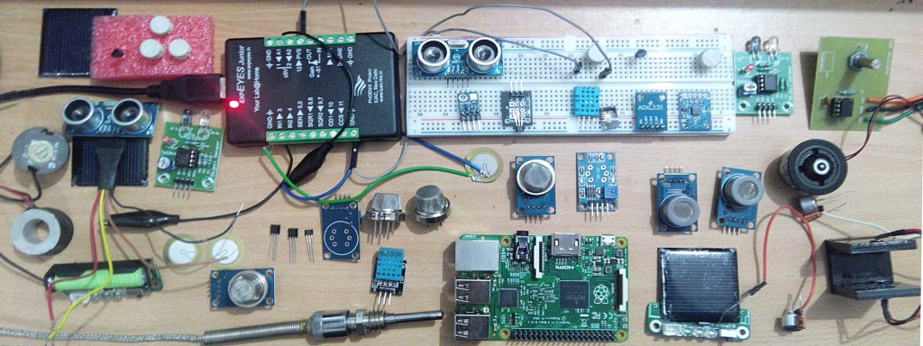
My GSoC Gallery of Sensors and Devices: Here are all the sensors I played with for PSLab..

The complete list of sensor plug-ins developed is available at http://gnovi.edublogs.org/2015/08/21/gsoc-2015-with-fossasia-list-of-sensor-plug-ins-developed-for-expeyes/

Sensor Plugins for ExpEYES

The aim of my project is to develop new Sensor Plug-ins for ExpEYES to measure a variety of parameters like temperature, pressure, humidity, wind speed, acceleration, tilt angle, magnetic field etc. and to provide low-cost open source laboratory equipment for students and citizien scientists all over the world.

We are enhancing the scope of ExpEYES for using it to perform several new experiments. Developing a low-cost stand alone data acquisition system that can be used for weather monitoring or environmental studies is another objective of our project.

I am happy to see that the things have taken good shape with additional gas sensors added which were not included in the initial plan and we have almost achieved all the objectives of the project, except for some difficulties in calibrating sensor outputs and documentation. This issue will be solved in a couple of days.

Experimenting with different sensors in my kitchen laboratory

I started exploring and experimenting with different sensors. After doing preliminary studies I procured analog and a few digital sensors for measuring weather parameters like temperature, relative humidity and barometric pressure. A few other sensors like low cost piezoelectric sensor, accelerometer ADXL-335, Hall effect magnetic sensor, Gyro-module etc were also added to my kitchen laboratory. We then decided to add gas sensors for detecting Carbon Monoxide, LPG and Methane.

With this development ExpEYES can now be used for pollution monitoring and also in safety systems in Physics/chemistry laboratory. The work on the low-cost Dust Sensor is under progress.

Challenges, Data Sheet, GUI programs

I had to spend a lot of time in getting the sensor components, studying their data sheets, soldering and setting them up with ExpEYES. And then little time in writing GUI Programs. I started working almost 8 to 10 hours every evening after college hours (sometimes whole night) and now things have taken good shape.

Thanks to my mentor at FOSSASIA for pushing me, sometimes with strict words. I could add many new sensor plug-ins to ExpEYES and now I will also be working on Light sensors so that the Pocket Science Lab can be used in optics. With these new sensor plug-ins one can replace many costly devices from Physics, Chemistry, Biology and also Geology Lab.

What’s next? My Plan for next steps

  • Calibration of sensor data

  • Prototyping stand-alone weather station

  • Pushing data to Loklak server

  • Work on PSLab@Fossasia website

  • Fossasia Live Cd based on Lubuntu with ExpEYES and other educational softwares

  • Set-up Documentation for possible science experiments with the sensor plug-ins and low-cost, open source apparatus

Continue ReadingA low-cost laboratory for everyone: Sensor Plug-ins for ExpEYES to measure temperature, pressure, humidity, wind speed, acceleration, tilt angle and magnetic field