A Workflow of Auto Executing Services on SUSI.AI Smart Speaker

As we plan to create a headless client on RaspberryPi, the requirement was that the SUSI.AI programs should run automatically. To do so, we had to figure out a way to boot up various scripts on startup.

We had the following options to execute the scripts on startup:

  1. Editing Rc.local file
  2. Systemd Rules
  3. Crontab

We decided to proceed with Systemd Rules because using Rc.local and Crontab requires modifying the default system files which in case of any error would make the os functionalities to crash very soon.

We then created the SystemD rules for the following services:

1.factory-daemon.service
2. python-flask.service
3. susi-server.service
4. update-daemon.service
5. susi-linux.service

Now I’ll demonstrate the working and the functionality of each service being implemented.

1. Factory-Daemon Service

This service initiates the factory daemon with the raspberry Pi startup and then keeps it running continuously looking for any input from the GPiO port.

[Unit]
Description=SUSI Linux Factory Daemon
After=multi-user.target

[Service]
Type=simple
ExecStart=/usr/bin/python3 /home/pi/SUSI.AI/susi_linux/factory_reset/factory_reset.py

[Install]
WantedBy=multi-user.target

2. Python-Flask Service

This service starts a python Server to allow handshake between mobile apps and the Smart Speaker which will allow the user to configure SUSI Smart Speaker accordingly.

[Unit]
Description=Python Server for SUSI Linux
After=multi-user.target

[Service]
Type=simple
ExecStart=/usr/bin/python3  /home/pi/SUSI.AI/susi_linux/access_point/server/server.py

[Install]
WantedBy=multi-user.target

3.SUSI-Server Service

This service starts the Local SUSI Server as soon as the Raspberry Pi starts up which in turn allows the SUSI Linux programs to fetch responses of queries very quickly.

[Unit]
Description=Starting SUSI Server for SUSI Linux
After=multi-user.target

[Service]
Type=oneshot
ExecStart=/home/pi/SUSI.AI/susi_linux/susi_server/susi_server/bin/restart.sh

[Install]
WantedBy=multi-user.target

4. Update-Daemon Service

This Service creates a Daemon which starts with the Raspberry Pi and fetches the latest updates from the repository from the upstream branch.

[Unit]
Description=Update Check- SUSI Linux
Wants=network-online.target
After=network-online.target

[Service]
Type=oneshot
ExecStart=/home/pi/SUSI.AI/susi_linux/update_daemon/update_check.sh

[Install]
WantedBy=multi-user.target

5. SUSI-Linux Service

This Service finally runs the main SUSI Linux software after everything has started.

[Unit]
Description=Starting SUSI Linux
Wants=network-online.target
After=network-online.target

[Service]
Type=idle
WorkingDirectory=/home/pi/SUSI.AI/susi_linux/
ExecStart=/usr/bin/python3 -m main

[Install]
WantedBy=multi-user.target

This blog gives a brief workflow of auto-executing services on SUSI Smart Speaker.

Resources

Continue ReadingA Workflow of Auto Executing Services on SUSI.AI Smart Speaker

Displaying SUSI Smart speaker under Devices while logging in

The user should be given an ability to access all his devices on one page(Smart Speaker, IOS Device, WebClient and the Android Device). The user was previously allowed to access his/her web app account, the IOS app, Android App. But not the Smart Speaker. Now, this feature will allow the user to easily manage the Smart Speaker devices without many hassles.

In this post, we will be talking about the API’s that we have used to send the details of the Smart-Speaker to the server.

About the API’s

  1. Below is the API endpoint which will return the list of all devices present under the user’s account

We use the following endpoint

/aaa/ListUserSettings.json?/access_token=access_token


Below is sample response :

“devices”: {
“8C-39-45-cc-eb-95”: {
“name”: “Device 1”,
“room”: “Room 1”,
“geolocation”: {
“latitude”: “52.34567”,
“longitude”: “62.34567”
}
 }
}


  1. The second endpoint that we will be using is to add a new Device under the devices section

API Endpoint

/aaa/addNewDevice.json?


This endpoint has the following parameters

  • macid (Mac address of the device)
  • name (Name of the device)
  • room (Room info of the device)
  • latitude (Latitude info of the device)
  • longitude (Longitude info of the device)


After successfully hitting the endpoint , you’ll get the following response


{
“accepted”: true,
“message”: “You have successfully added the device!”,
“session”: {“identity”: {
“type”: “email”,
“name”: “sansyrox@gmail.com”,
“anonymous”: false
}}
}


Implementing the API’s

  1. First, we check the server for existing devices. This step is implemented primarily to check weather our current Smart Speaker is already configured or not.
get_device_info = api_endpoint + ‘/aaa/listUserSettings.json?’

param1 = {
       ‘access_token’:access_token
   }

   # print(access_token)

   if access_token is not None:
       device_info_response = requests.get(get_device_info,param1)
       device_info = device_info_response.json()

   # print(device_info)

If the current device is not already configured on Server, we proceed to next step.

  1. Now we will configure the device with the server and then post the device settings there.
    We will implement the API in the following way:


if device_info is not None:
   device = device_info[‘devices’] # list of existing mac ids
   print(device)
   session = device_info[‘session’] # session info
   identity = session[‘identity’]
   name = identity[‘name’]
   
   params2 = {
   ‘macid’: macid,
   ‘name’: name,
   ‘device’: ‘Smart Speaker’,
   ‘access_token’: access_token
   }

   for dev in device:
       if dev == macid:
           print(‘Device already configured’)
           return
       else :
           adding_device = requests.post(add_device_url, params2)
           print(adding_device.url)


To extract the mac address from the speaker and pass it as the params , we use a python library called UUID and this is how SUSI Smart Speaker is displayed on the web client(chat.susi.ai).

Resources

Tags


Continue ReadingDisplaying SUSI Smart speaker under Devices while logging in

Creating an Update Daemon for SUSI Smart Speaker

A daemon in reference of operating systems is a computer program that runs as a background process rather than under direct control of the user. Various daemons are being used in SUSI smart speaker.

The following daemons have been created

  • Update Daemon
  • Media Discovery Daemon
  • Factory Reset Daemon 

In this blog, we’ll be discussing the implementation of the Update Daemon in SUSI.AI

Update Daemon

Due to the ever-growing coding community, it is needed to provide regular updates to the smart speaker and keep it in sync with the latest technology. Hence an Update Daemon was required that could fetch updates at a regular interval.

The Updated Daemon was implemented in the following steps

1.Deciding the Update Interval

How frequently should we check for updates was the first question that was tackled while implementing this daemon.
We decided that we should check for Update, every time the Raspberry Pi starts and an internet connection was available.

2. Implementing The Decision

To start the Update script every time the Raspberry Pi starts, we decided to create Systemd rules.

[Unit]
Description=Update Check- SUSI Linux
Wants=network-online.target
After=network-online.target

[Service]
Type=oneshot
ExecStart=/home/pi/SUSI.AI/susi_linux/update_daemon/update_check.sh

[Install]
WantedBy=multi-user.target

The above rule waits for a network connection to be established with the Raspberry Pi and then triggers a bash script that fetches updates

3. Fetching The Updates


Now, a bash script was prepared that would fetch the latest changes from the online repo and merge the latest changes in the local repo


#!/bin/sh

UPSTREAM=${1:-‘@{u}’}
LOCAL=$(git rev-parse @)
REMOTE=$(git rev-parse “$UPSTREAM”)
BASE=$(git merge-base @ “$UPSTREAM”)
CHECK=”
if [ $LOCAL = $REMOTE ]
then
   echo “Up-to-date”
   CHECK=’up-to-date
elif [ $LOCAL = $BASE ]
then
   echo “Need to pull”
   CHECK=”Need-to-pull”
else
   echo “Diverged”
fi

if [$CHECK = “Need-to-pull”]
then
   git fetch UPSTREAM
   git merge UPSTREAM/master
fi


Resources

Tags


susi.ai, gsoc, gsoc’18, fossasia, update, daemon, update_daemon, smart speaker, systemd, hardware

Continue ReadingCreating an Update Daemon for SUSI Smart Speaker

Creating step designs from KiCAD for PSLab

PSLab hardware device is developed using KiCAD. It is an open source PCB designing tool which we can use for free and it has almost all the features needed to build a professional PCB. But it lacks one thing. It cannot generate and export 3D models. In fact there is a 3D viewer in KiCAD but there is no way to export it. When manufacturing PSLab devices, it was required by the manufacturers so that they can have a clear understanding how the components are placed. This step is necessary for them to design the production line.

Before we get started, there are few prerequisites to help us get this done. They are as follows;

  1. FreeCAD: Open source 3D modeling software
  2. KiCAD step up tools: External library to import KiCAD PCB layouts to FreeCAD

You may need to follow installation instructions to install FreeCAD from the link given. Once we are all set, extract the KiCAD Stepup tools. There we can find a set of python libraries and some bash scripts. We can either use the scripts or type commands ourselves. I found scripts having some issues configuring paths.

To fire up FreeCAD with KiCAD stepup tools enabled, type the following command on your console;

$ freecad kicad-StepUp-tools.FCMacro

Make sure the console is pointing to the directory where the FCMacro file is located. This will open up FreeCAD and if you opened it already and saw the opening screen of FreeCAD, you’d notice a whole new toolbar is added.

Here you can see many tools related to import and export step files and 3D models from outside libraries and folders. Each tool is specific;

  • Load-kicad-footprint:

This tool is useful to generate a step file for an individual PCB component, say a resistor into a step file.

  • Export-to-kicad:

There are instances where when we design a custom foot print, and KiCAD doesn’t have the 3D model. In such a case we can export such a model to KiCAD

  • Load-kicad:

This is the tool we are using to export PSLab PCB board to step format. Before we move on to this tool there is one last configuration we have to do. FreeCAD doesn’t know where we have put KiCAD 3D models. This library simply transforms the available 3D models in KiCAD into step files and build the final output combining all of them together as in the featured image of this blog post. To setup the 3D model path, in KiCAD, there is a path configuration option. Copy the path under “KISYS3DMOD”.

Figure 2: Path Configuration dialog box in KiCAD

And paste it into the ini file named “ksu-config.ini” which you can find in home folder.

Figure 3: Place to add 3D model path in ksu-config.ini file

Once that is done, click on the Load-KiCAD tool icon and browse to the repository where the PSLab hardware files are located at. Open the board file and FreeCAD will generate part by part and finally output the complete design. Now we can export the design in plenty of formats such as steps, stl another similar file format and many more.

Reference:

  1. https://www.freecadweb.org/wiki/Download
  2. http://kicad-pcb.org/external-tools/stepup/
Continue ReadingCreating step designs from KiCAD for PSLab

Using external UART modules to debug PSLab operations

Pocket Science Lab by FOSSASIA is a compact tool that can be used for circuit analytics and debugging. To make things more interesting, this device can be accessed via the user interface using an Android app or also a desktop app. Both these apps use the UART protocol (Universal Asynchronous Receiver-Transmitter) to transmit commands to the PSLab device from mobile phone or PC and receive commands vice versa. The peculiar thing about hardware is that the developer cannot simply log data just like developing and debugging a software program. He needs some kind of an external mechanism or a tool to visualize those data packets travelling through the wires.

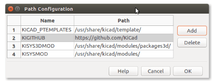
Figure 1: UART Interface in PSLab

PSLab has a UART interface extracted out simply for this reason and also to connect external sensors that use the UART protocol. With this, a developer who is debugging any of the Android app or the desktop app can view the command and data packets transmitted between the device and the user end application.

This  requires some additional components. UART interface has two communication related pins: Rx(Receiver) and Tx(Transmitter). We will need to monitor both these pin signals for input and output data packets. It should be kept in mind that PSLab is using 3.3V signals. This voltage level is important to mention here because if someone uses 5V signals on these pins, it will damage the main IC. There are FTDI modules available in market. FTDI stands for Future Technology Devices International which is a company name and their main product is this USB transceiver chip. These chips play a major role in electronic industry due to product reliability and multiple voltage support. PSLab uses 3.3V USB Tx Rx pins and modules other than FTDI wouldn’t support it.

Figure 2: FTDI Module from SparkFun

The module shown in Fig.2 is a FTDI module which you can simply plug in to computer and have a serial monitor interface. There are cheaper versions in shopping websites like eBay or Alibaba and they will also work fine. Both Tx and Rx pins will require two of these modules and connectivity is as follows;

PSLab [Rx Pin] → FTDI Module 1 [Rx Pin]
PSLab [Tx Pin] → FTDI Module 2 [Rx Pin]

This might look strange because everywhere we see a UART module is connected Rx → Tx and Tx → Rx. Notice that our idea is to monitor data packets. Not communicate with PSLab device directly. We want to see if our mobile phone Android app is sending correct commands to PSLab device or not and if PSLab device is transmitting back the expected result or not. This method helped a lot when debugging resistance measurement application in PSLab Android app.

Monitoring these UART data packets can be done simply using a serial monitor. You can either download and install some already built serial monitors or you can simply write a python script as follows which does the trick.

import serial

ser = serial.Serial(
    port='/dev/ttyUSB1',
    baudrate=1000000000
)

ser.isOpen()
while 1 :
    data = ''
    while ser.inWaiting() > 0:
        data += ser.read(1)

    if data != '':
        print ">>" + data

Once you are getting commands and responses, it will look like debugging a software using console.

References:

  1. PySerial Library : http://pyserial.readthedocs.io/en/latest/shortintro.html
  2. UART Protocol : https://en.wikipedia.org/wiki/Universal_asynchronous_receiver-transmitter
  3. FTDI : https://en.wikipedia.org/wiki/FTDI
Continue ReadingUsing external UART modules to debug PSLab operations

Connecting to a Raspberry Pi through a SSH connection Wirelessly

The tech stack of the SUSI.AI smart speaker project is mainly Python/Bash scripts. Every smart speaker has an essential feature that allows the user’s mobile device to connect and give instructions to the speaker wirelessly. To make this connection possible, we are trying to implement this using an SSH connection.

Why SSH?

SSH(a.k.a Secure Shell) is a cryptographic connection which allows secure transfer of data even over an unsecured connection.SSH connection even allows TCP as well as X11 forwarding which are an added bonus.

Step 1: Initial Setup

  • Both the raspberry Pi with raspbian installed and the mobile device should be on a same wireless network
  • One should have an SSH viewer like JuiceSSH(Android) and iTerminal(IOS) installed on their mobile devices
  • Now we must enable SSH on our raspberry Pi

Step 2: Enabling SSH on Raspberry PI

  • To enable SSH on your Pi , follow the steps mentioned below:
Menu > Preferences > Raspberry Pi Configuration.

Choose the interfaces tab and enable SSH

Step 3:Setting Up the client


  • Login to your raspberry pi as the root user (pi by default)
  • Type the following command to know the broadcasting ip address
pi@raspberrypi:hostname -I


  • Now , open the client on your mobile device and add the configurations

By default the username of the system is ‘pi’ and the password is ‘raspberry’

Step 4: Changing the default SSH password

Since the default password of every RaspberryPi is the same. So , the pi can be accessed by any device that has access to the local network which is not a secure way of accessing the device

  • In the SSH window type ‘passwd’
  • Type the current password
  • Type the new password
  • Re-enter the new password

Now you will be able to login to your raspberry through an SSH connection

Resources


Tags

Fossasia, gsoc, gsoc’18, susi, susi.ai, hardware,susi_linux

Continue ReadingConnecting to a Raspberry Pi through a SSH connection Wirelessly

Creating Bill of Materials for PSLab using KiCAD

PSLab device consists of a hundreds of electronic components. Resistors, diodes, transistors, integrated circuits are to name a few. These components are of two types; Through hole and surface mounted.

Surface mount components (SMD) are smaller in size. Due to this reason, it is hard to hand solder these components onto a printed circuit board. We use wave soldering or reflow soldering to connect them with a circuit.

Through Hole components (TH) are fairly larger than their SMD counter part. They are made bigger to make it easy for hand soldering. These components can also be soldered using wave soldering.

Once a PCB has completed its design, the next step is to manufacture it with the help of a PCB manufacturer. They will require the circuit design in “gerber” format along with its Bill of Materials (BoM) for assembly. The common requirement of BoM is the file in a csv format. Some manufacturers will require the file in xml format. There are many plugins available in KiCAD which does the job.

KiCAD when first installed, doesn’t come configured with a BoM generation tool. But there are many scripts developed with python available online free of charge. KiBoM is one of the famous plugins available for the task.

Go to “Eeschema” editor in KiCAD where the schematic is present and then click on the “BoM” icon in the menu bar. This will open a dialog box to select which plugin to use to generate the bill of materials.

Initially there won’t be any plugins available in the “Plugins” section. As we are adding plugins to it, they will be listed down so that we can select which plugin we need. To add a plugin, click on the “Add Plugin” button to open the dialog box to browse to the specific plugin we have already downloaded. There are a set of available plugins in the KiCAD installation directory.

The path is most probably will be (unless you have made any changes to the installation);

usr/lib/kicad/plugins

Once a plugin is selected, click on “Generate” button to generate the bom file. “Plugin Info” will display where the file was made and it’s name.

Make sure we have made the BoM file compatible to the file required by the manufacturer. That is; removed all the extra content and added necessary details such as manufacturer’s part numbers and references replacing the auto generated part numbers.

Resources:

Continue ReadingCreating Bill of Materials for PSLab using KiCAD

Basics behind BJT and FET experiments in PSLab

A high school student in his curriculum; will come across certain electronics and electrical experiments. One of them related to semiconductor devices such as Bipolar Junction Transistors (BJTs) and Field Effect Transistors (FETs). PSLab device is capable of function as a waveform generator, voltage and current source, oscilloscope and multimeter. Using these functionalities one can design an experiment. This blog post brings out the basics one should know about the experiment and the PSLab device to program an experiment in the saved experiments section.

Channels and Sources in the PSLab Device

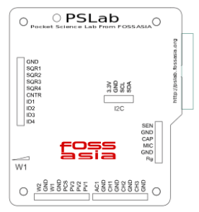
The PSLab device has three pins dedicated to function as programmable voltage sources (PVS) and one pin for programmable current source (PCS).

Programmable Voltage Sources can generate voltages as follows;

  • PV1 →  -5V ~ +5V
  • PV2 → -3.3V ~ +3.3V
  • PV3 → 0 ~ +3.3V

Programmable Current Source (PCS) can generate current as follows;

  • PCS → 0 ~ 3.3mA

The device has 4 channel oscilloscope out of those CH1, CH2 and CH3 pins are useful in experiments of the current context type.

About BJTs and FETs

Every semiconductor device is made of Silicon(Si). Some are made of Germanium(Ge) but they are not widely used. Silicon material has a potential barrier of 0.7 V among P type and N type sections of a semiconductor device. This voltage value is really important in an experiment as in some practicals such as “BJT Amplifier”, there is no use of a voltage value setting below this value. So the experiment needs to be programmed to have 0.7V as the minimum voltage for Base terminal.

Basic BJT experiments

BJTs have three pins. Collector, Emitter and Base. Current to the Base pin will control the flow of electrons from Emitter to Collector creating a voltage difference between Collector and Emitter pins. This scenario can be taken down to three types as;

  • Input Characteristics → Relationship between Emitter current to VBE(Base to Emitter)
  • Output Characteristics → Relationship between IC(Collector) to VCB(Collector to Base)
  • Transfer Characteristics → Relationship between IC(Collector) to IE(Emitter)

Input Characteristics

Output Characteristics

Transfer Characteristics


Basic FET experiments

FETs have three pins. Drain, Source and Gate. Voltage to Gate terminal will control the electron flow from either direction from or to Source and Drain. This scenario results in two types of experiments;

  • Output Characteristics → Drain current to Drain to Source voltage difference
  • Transfer Characteristics → Gate to Source voltage to Drain current
Output Characteristics Transfer Characteristics

Using existing methods in PSLab android repository

Current implementation of the android application consists of all the methods required to read voltages and currents from the relevant pins and fetch waveforms from the channel pins and output voltages from PVS pins.

ScienceLab.java class – This class implements all the methods required for any kind of an experiment. The methods that will be useful in designing BJT and FET related experiments are;

Set Voltages

public void setPV1(float value);

public void setPV2(float value);

public void setPV3(float value);

Set Currents

public void setPCS(float value);

Read Voltages

public double getVoltage(String channelName, Integer sample);

Read Currents

To read current there is no direct way implemented. The current flow between two nodes can be calculated using the PVS pin value and the voltage value read from the channel pins. It uses Ohm’s law to calculate the value using the known resistance between two nodes.

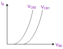
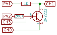
In the following schematic; the collector current can be calculated using known PV1 value and the measured CH1 value as follows;

IC = (PV1 – CH1) / 1000

This is how it is actually implemented in the existing experiments.

If one needs to implement a new experiment of any kind, these are the basics need to know. There can be so many new experiments implemented using these basics. Some of them could be;

  • Effect of Temperature coefficient in Collector current
  • The influence in β factor in Collector current

Resources:

Continue ReadingBasics behind BJT and FET experiments in PSLab

Using Hierarchical Blocks in KiCAD to Collaborate in PSLab Hardware Development

The PSLab hardware project designed in KiCAD, an ECAD tool; doesn’t support collaborative features like Git providing for software projects. As explained in a previous blog post on techniques to help up with project collaboration, this blog post will demonstrate how two developers can work together on the same hardware project.

The difficulties arise as the whole project is in one big schematic file. Editing made by one developer will affect to the editing done by the other developers causing merge conflicts. KiCAD doesn’t compile nicely if the changes were fixed manually most of the cases.

The solution practiced in the pslab-hardware project is using hierarchical blocks. This blog post will use a KiCAD project with an oscillator implementation and a voltage regulator implementation just like the ones in pslab-hardware schematics. To avoid complications in understanding changes in a huge circuit, only these two modules will be implemented separately in the blog.

Initially the project will look like the following figure;

Sheet1 Sheet2

These two hierarchical blocks will be created as different .sch files in the project directory as follows;

Assume two different developers are working on these two different blocks. That is the key concept in collaborating hardware projects in KiCAD. As long as the outer connections (pins) don’t get changed, edits made to one block will have no effect on the other blocks.

Developer 1 decided that the existing power circuit is not efficient for the PSLab device. So he decided to change the circuit in Sheet 1. The circuit before and after modification is shown in the table below.

Sheet 1 (Before) Sheet 1 (After)

If we take a look at the git status now, it will be as follows;

From this it is noticeable that neither the main schematic file nor Developer2.sch hasn’t been touched by the edits made to Developer1.sch file. This avoids merge conflicts happening when all the developers are working on the same schematic file.

Resources :

Continue ReadingUsing Hierarchical Blocks in KiCAD to Collaborate in PSLab Hardware Development

Create a Distance Sensor using PSLab

PSLab device is a small lab which supports a ton of features. Among its many features, integrating a distance measuring sensor like HC SR04 sonar sensor into it is one of them. This blog post will bring out the basic concepts behind a sonar sensor available in the current market, how it measures distance and how it is implemented in the PSLab device.

A sonar sensor uses a sound wave with a very high frequency. These waves are called ultrasonic waves. They cannot be heard by the naked ear. Human ear can only hear frequencies from 20 Hz up to 20 kHz. Generally HC SR04 sensors use a wave with frequency as high as 40 kHz so this makes sense. The basic principal behind the sensor is the reflectance property of sound. Time is calculated from the transmission time up to the time receiving the reflected sound wave. Then using general moment equation S = ut; with the use of speed of sound, the distance can be measured.

The figure shows a HC SR04 ultrasound sensor. They are quiet famous in the electronic field; especially among hobbyists in making simple robots and DIY projects. They can be easily configured to measure distance from the sensor up to 400 cm with a measuring angle of 15 degrees. This angular measurement comes into action with the fact that sound travels through a medium in a spherical nature. This sensor will not give accurate measurements when used for scenarios like measuring distance to very thin objects as they reflect sound poorly or there will not be any reflectance at all.

There are four pins in the HC SR04 sonar sensor. Corner pins in the two sides are for powering up the Sonar sensor. The two pins named ECHO and TRIG pins are the important pins in this context. When the TRIG pin (Trigger for short) is excited with a set of 8 square pulses at a rate of 40 kHz, the ECHO pin will reach to logic HIGH state which is the supply voltage (+5 V). When the transmitted sound wave is reflected back to the sensor, this high state of the ECHO pin will shift to logic LOW state. If a timer is turned on when the ECHO pin goes to logic HIGH state, we can measure how long it was taken for the sound beam to return to the sensor by turning off the timer when the ECHO pin goes to logic LOW state.

Having described the general implementation of a sonar sensor; a similar implementation is available in PSLab device. As mentioned earlier, TRIG pin requires a triggering pulse of 8 set of square waves at 40 kHz. This is achieved in PSLab using SQR pulse generating pins. The time is measured from the transmitting point until the receiving point to evaluate the distance. The real distance to the obstacle in front of the sensor can be calculated using following steps;

  1. Measure total round trip time of the sound beam. Take it as t
  2. Calculate the time taken for the beam to travel from sensor to the obstacle. It will be t/2
  3. Use motion equation S = ut to calculate the actual distance taking u = speed of sound in air. Substituting the time value calculated in step 2 to t, S will produce the distance

Resources:

Continue ReadingCreate a Distance Sensor using PSLab