In the Neurolab-Android app, we have been using an Arduino board for development as a workaround to the actual Neurolab hardware which is currently in the manufacturing stages. Along with the Arduino, we use a Micro SD card module with an SD card attached containing a dataset file in it. This combination of the Arduino and the SD card module serves as the source of dataflow into the Android app.
Firstly, we need to get the Arduino programmed for reading the dataset file from the SD card in the SD card module. We program the Arduino using the Arduino IDE on any desktop platform.
1. Import required libraries before starting off, namely the SPI and SD libraries for serial communication and SD card related functions respectively. Let us also set up some constant values which are going to be used in various parts of the code needed to program the Arduino for our required purpose.
The ‘chipSelect’ variable denotes the chip select pin number for the connected Micro SD card adapter (module).
The baud rate for the Arduino board has been set to 9600 as a default. The dataset stored in the SD card from which the data needs to be read has been named “Dataset1”.
2. Next, we will need to initialize the SD card to check even if an SD card is inserted or not in the SD card module. We create a function for this purpose named ‘initializeSDCard’ in the following way:
The function will return true if initialization was successful. An unsuccessful initialization may also be due to the fact of SD card corrupted apart from not being properly inserted into the module.
3. Now we will be opening the dataset file from the SD card, making it ready to be read from.
The function will take in the file name as an argument and open it from the SD card. If the file is not found in the SD card, it will simply print out an error message to the serial output. It returns the file object in a true or false context accordingly.
4. We are now going to read data from the dataset in the SD card line by line using a function. The dataset file instance is passed as an argument to this function. This file is read and transmitted over the serial output channel line by line with ‘\n’ as the line delimiter, skipping null lines.
This function will keep reading from the file untill it has nothing more i.e till the end of file.
5. Next, we update the setup function which is the function to be executed for the programming of the Arduino board. Here, we call our defined functions according to our need logical need.
In the Neurolab-Android app, we have a feature for recording data. It uses data incoming from the hardware device and stores it in a data table format with various parameters. Two of these parameters happened to be the latitude and longitude (location) of the user using the app. For that, we needed to implement a location tracking feature which can be used while recording the data in the data table.
Let’s start off with adding the required permission uses in the Android Manifest file.
These will be used to ask permissions from the user to access the devices’ internet and location/GPS.
Now, we will be making our Location Tracker class that will be used in tracking the location and getting the corresponding latitude and longitude.
Firstly, we are going to define some variables – an array of manifest permissions for enabling GPS, some constant values for requesting specific permissions, a provider for the GPS provider.
We also need to initialize and have a location manager ready to request location updates from time to time. Defining a locationManager need to get the system service for location. We define it in the following way:
Firstly, we need to check for the runtime permissions required for our task. We achieve this with the function ‘checkRuntimePermissions’ which we have created in a utility class named ‘PermissionUtils’. The code of this utility class can be found here: PermissionUtils.java. It basically self checks individual permissions from the array passed in the arguments with the Android system.
We then use the location manager instance to request current location updates using the constants and the location listener we defined earlier.
So now, that we have started capturing the user device location, we can get the device Location object values (latitude and longitude).
This method requests the location and returns a Location object. If there is an internet connection problem or the device location is disabled from the device settings, it returns a default location object. Here in the Neurolab project, we had set the default location latitude and longitude to 0.0.
Now we can use this location while creating the recorded file in our app directory which can be used after importing that recorded file in the app. We will be storing the location in two columns in the recorded file which is in a table format.
We write the latitude and longitude of the device in the file using a PrintWriter object and get the latitude and longitude of the device in the following way:
long latitude = locationTracker.getDeviceLocation().getLatitude()long longitude = locationTracker.getDeviceLocation().getLongitude()
Then, using the PrintWriter object we can write the data into the file in the following way:
PrintWriter out =new PrintWriter(new BufferedWriter(new FileWriter(csvFile,true)));
out.write(data +"\n");
Here, the ‘data’ contains the latitude and longitude converted to String type.
That’s it! Now you can use the LocationTracker object to capture the location and get the current device location using it in your own app as well.
Hope this blog, adds value to your Android development skills.
In the development process of the Neurolab Android, we needed an Arduino-Android connection for transfer of data from datasets which included String and float data type values. In this blog post, I will show you how to establish a serial communication channel between
Android and Arduino through USB cable through which we can transmit data bidirectionally.
Requirements
Hardware:
Android Phone
Arduino (theoretically from any type, but I’ll be using Arduino Uno)
We need to program the Arduino to send and receive data. We achieve that with the help of Arduino IDE as mentioned above. Verify, compile and upload a sketch to the Arduino for sending and receiving data. If you are a complete beginner in Arduino programming, there are example sketches for this same purpose. Load an example sketch from under the communication segment and choose the serial communication sketch. Here, we will be working with a simple sketch for the Arduino such that it simply echoes whatever it receives on the serial port. Here is sketch code:
// the setup routine runs once when you press reset:voidsetup(){// initialize serial communication at 9600 bits per second:
Serial.begin(9600);}// the loop routine runs over and over again forever:voidloop(){char incomingByte;// If there is a data stored in the serial receive buffer, read it and print it to the serial port as human-readable ASCII text.if(Serial.available()){
incomingByte = Serial.read();
Serial.print(incomingByte);}}
Feel free to compile and upload it to your own Arduino.
2. Working with Android:
Firstly, we need an USBManager instance initialized with the system service – ‘USB_SERVICE’. This needs to be done in an Activity (preferably main) so that this instance can be passed to the Communication Handler class, which we are going to create next.
Now, we will be working with a class for handling the serial communications with our Android device and the Arduino board. We would pass the USBManager instance to this class wherein work will be done with that to find the USBDevice and USBDeviceConnection
Starting with, we need to search for any attached Arduino devices to the Android device. We create a method for this and use the ‘getDevicesList’ callback to achieve this in the following way:
c. Now, in the Activity where we will be testing or intend to work with the serial connection, we check for the usb permission in a broadcast receiver which is registered in the onCreate method of the activity along with an Intent Filter. The Intent filter has the usp permission as an action added to it.
d. In the onReceive callback of the broadcast receiver, if the usb permission is granted, we initialize the serial connection with a baud rate for our Arduino device. In this initialization method, we get the connection and serial port of the connected Arduino to the Android device with which we can work. The method is implemented in the following way:
e. Now, with this ‘serialPort’ we can read data from the Arduino in the UsbReadCallback callback from the USBSerialInterface. The data is read in the form of array of bytes. This read data can be used to carry out the various functionalities we want to achieve.
With the above steps we can establish a serial connection between Android and Arduino, transmit data from Arduino to Android device for processing.
The whole working source code of the Neurolab Android project can be found here:
In Android App development, implementation of Android Charts play an integral part in developing database oriented apps, be it casual or professional apps.
Data Analysis plays an integral part in various sectors and industries in today’s world. In sports, e.g- cricket, we see the use of charts like bar charts, line charts in various stages of the game to present the game and score analysis.
In healthcare, we see the use of live real time graphs to show human health analysis like the heart rate, brain waves, etc. In the IT industry, professionals use graphical data analysis for their presentations in meetings and conferences.
I have been working with FOSSASIA on the Neurolab Android App, where I had to work on this unique program mode called “Memory Graph” wherein I had to work extensively with MPAndroidChart library. While working, I understood the various use cases of charts and graphs on the Android platform. In this blog, I want to showcase the building of one part of the app with a proper tutorial.
Tutorial
In the Android SDK, we, the developers have been given the benefit of a tool known as GraphView. But this view being a very default and basic tool in the toolkit, has limitations in terms of customization, needs a lot of boilerplate code to set up the base to work upon.
Also plotting real time graphs becomes a challenge while using the GraphView.
In this tutorial, we will be focusing on the Memory Graph program mode of the app wherein we will be using an external library – MPAndroidChart to help us achieve our aim.
Memory Graph
1. Firstly, open the app level build.gradle and implement the library dependency in there.
Note – The library version may change depending upon the time you are reading this blog. Refer here for the latest library updates.
XML layout
1. The layout for our chart screen should be simple without any other components on the screen so that it is perfectly comfortable for the users to understand the graph and not get overwhelmed. Here, we are going to use a RelativeLayout as the parent to the Chart. For our Memory graph program mode, I worked with the LineChart view from the MPAndroidChart library. The xml code for the layout:
1. In the onCreate method of our MemoryGraph Activity, we set the layout parameters as flags for our chart layout to use of the screen window. We find the LineChart from the layout by its id and bind it up using the private variable which is going to be used to set it up programmatically. Here is the code for the onCreate method:
2. We are going to create a method named initGraph to set up the graph and make it ready to plot the data in real-time. Here is the code for the method:
graph.setOnChartValueSelectedListener(this);// enable description text
graph.getDescription().setEnabled(true);// enable touch gestures
graph.setTouchEnabled(true);// enable scaling and dragging
graph.setDragEnabled(true);
graph.setScaleEnabled(true);
graph.setDrawGridBackground(false);// if disabled, scaling can be done on x- and y-axis separately
graph.setPinchZoom(true);// set an alternative background color
graph.setBackgroundColor(getResources().getColor(R.color.memory_graph_background));
LineData data =new LineData();
data.setValueTextColor(Color.WHITE);// add empty data
graph.setData(data);
graph.getDescription().setText(getResources().getString(R.string.axis_desc_time));
graph.getDescription().setTextColor(Color.WHITE);// get the legend (only possible after setting data)
Legend l = memGraph.getLegend();// modify the legend ...
l.setForm(Legend.LegendForm.LINE);
l.setTextColor(Color.WHITE);
XAxis xl = graph.getXAxis();
xl.setTextColor(Color.WHITE);
xl.setDrawGridLines(false);
xl.setAvoidFirstLastClipping(true);
xl.setEnabled(true);
YAxis leftAxis = graph.getAxisLeft();
leftAxis.setTextColor(Color.WHITE);
leftAxis.setAxisMaximum(100f);
leftAxis.setAxisMinimum(0f);
leftAxis.setDrawGridLines(true);
leftAxis.setGridColor(Color.WHITE);
YAxis rightAxis = graph.getAxisRight();
rightAxis.setEnabled(false);
Now, in here to use the setOnChartValueSelectedListener callback we need to implement the OnChartValueSelectedListener interface in our Activity. This will be required if the user clicks on a plot point. We need to set up the chart to respond to that user click on a particular data value on the chart.
3. Next, we are going to create a set of data for our graph to work with. As this set we create will be worked on by LineChart, hence our set will be of type LineDataSet. Using this LineDataSet, we will be able to set the axes labels, description, axes dependency (left or right), graph background, graph line colors and other necessary details. All parameters which can be tweaked through the `LineDataSet` for a LineGraph can be found here.
4. Now, that we have set up the data for our LineChart to be used, we would be moving on to plotting the data. Since, everybody would not be able to have datasets containing brain-wave data, we would be taking the help of the ‘random’ function provided in Java. We create a function called `addEntry()`, wherein we add a new ‘Entry’ to the data set. Here, as we are working with a single dataset (the set of random values), the index for our dataset in the LineChart, will be zero.
privatevoidaddEntry(){
LineData data = graph.getData();if(data !=null){
ILineDataSet set = data.getDataSetByIndex(0);if(set ==null){
set = createSet();
data.addDataSet(set);}
data.addEntry(new Entry(set.getEntryCount(),(float)(Math.random()*40)+30f),0);
data.notifyDataChanged();// let the graph know it's data has changed
graph.notifyDataSetChanged();// limit the number of visible entries
graph.setVisibleXRangeMaximum(120);// move to the latest entry
graph.moveViewToX(data.getEntryCount());}}
5. We then create data feeding function called ‘feedMultiple’, for the chart. It contains a new runnable, which calls the ‘addEntry’ function. We then execute that runnable in a UI thread from within a for-loop, thus creating continuous values to plot. Here is the code for the ‘feedMultiple’ function;
privatevoidfeedMultiple(){if(thread !=null)
thread.interrupt();final Runnable runnable =()-> addEntry();
thread =new Thread(()->{for(int i =0; i <1000; i++){// Don't generate garbage runnables inside the loop.
runOnUiThread(runnable);try{
Thread.sleep(25);}catch(InterruptedException e){
e.printStackTrace();}}});
thread.start();}
6. Now we can call our ‘feedMultiple’ method from the onCreate function of our MemoryGraph Activity java file and we are good to go!
In Android apps, we might have seen various instances in-app where we can import, export or save files. Now, where does the files go to or come from? There needs to be a specific folder or directory (maybe root) for a particular app which inturn contains the necessary files, the user has worked with from the app. In this blog, we will be learning about the backend of how to create directories and store files in them dynamically with proper content.
Context
I have been working with FOSSASIA on the project Neurolab-Android. In the app, we have various program modes, which has the option to save/record data. The saved data gets logged in a new file in the Neurolab directory/folder. Feel free to go ahead and explore the feature.
The Save/Record feature in Neurolab can be found in the app bar or as an option in the drop down menu present in the app bar itself in any program mode. The feature becomes functional, once the data is imported with the import data feature which is also present in the app bar.
Figure: Demonstration of features in Neurolab
Tutorial
Now, starting off, there are apps out there wherein users can save files from different segments in the app and those saved files can be used by the app itself at other times as they belong to that app itself specifically.
First off, we need to make sure we have a directory for our app, wherein the files will get stored. If the directory or folder is not present, it needs to be created.
Now, once the directory is present, we can go ahead to keep the saved files in it. Also we will be implementing category-wise storage of the files. Simply put, we will be storing csv files in the CSV folder, xls files in the Excel folder, etc. In the below code example, we see the use case of CSV ‘category’.
For saving a file in our app, we need to get (import) the file into our app. Once the file is imported, we can get the path of the file with the help of its URI. Let’s assign the path to a variable named ‘importedFilePath’. Then we place the imported file in the required category directory within our parent app directory depending and deciding upon the extension of the imported file.
Now, we have the ‘importedFile’ and the destination file path (dst) where the file needs to be stored for our app. The ‘extension’ can be of any type you feel the file should be. Here, for the fileName we are using the current date and time together.
Then, we can come to the function ‘transfer’ which has been called above.
privatestaticvoidtransfer(File src, File dst)throws IOException {
InputStream in =new FileInputStream(src);try{
OutputStream out =new FileOutputStream(dst);try{// Transfer bytes from in to outbyte[] buf =newbyte[1024];int len;while((len = in.read(buf))>0){
out.write(buf,0, len);}}finally{
out.close();}}finally{
in.close();}}
In the ‘transfer’ function, we initialize an input stream with the source file path and the output stream with the destination file path. We read the content in the form of a certain chunk of bytes from the source file and write to the output stream (destination file).
Finally, we close the output and input streams simultaneously.
Thus, we have our code ready to be bound by UI actions/buttons. Once, the user interacts with the action in your app, the imported file will get saved in the specific directory of your app.
That’s it. Hope this blog enhanced your Android development and Java skillset.
In the development process of the Neurolab Android app, we needed an Arduino-Android connection. This blog explains how to establish the connection and getting the Arduino board detected in my Android device
Context-connecting the board and getting it detected
Arduino boards are primarily programmed from the Desktop using the Arduino IDE, but they are not limited to the former. Android devices can be used to program the circuit boards using an application named Arduinodroid.
Arduino is basically a platform for building various types of electronic projects and the best part about it is that, it is open-sourced. Arduino, the company has got two products The physical programmable circuit board (often referred to as a microcontroller).
Examples of Arduino circuit boards – UNO, UNO CH340G, Mega, etc. Find more here.
Connecting the board and getting it detected
Arduino boards are primarily programmed from the Desktop using the Arduino IDE, but they are not limited to the former. Android devices can be used to program the circuit boards using an application named Arduinodroid.
In this blog, we are going to use Arduinodroid app for establishing a connection between the Arduino board and the Android device, getting the board detected in the Android phone and uploading a sketch to it.
Materials/Gadgets required:-
Arduino board (UNO preferably)
Arduino-USB Cable
OTG Cable
Android device
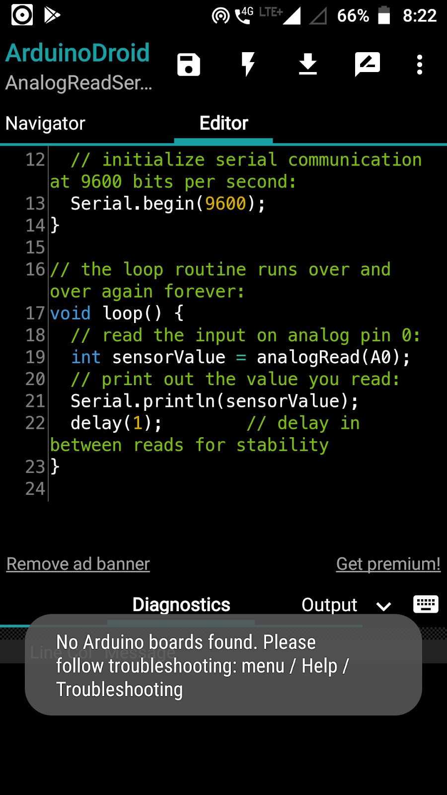
Now, one of the most frequent issues, while establishing a connection and getting the Arduino board detected with the Android device, is the error message of: “No Arduino boards detected” in the Arduinodroid app. There can be a few core reasons for this –
Your Android mobile device isn’t USB-OTG supported – Probably because it is an old model or it might be a company/brand-specific issue.
Disabled OTG Mode – Be sure to enable USB-OTG mode (only if your device has one) from the Developer options in your Android device settings.
Even after trying and making sure of these above points, if you still continue to get an error while uploading a sketch from the Arduinodroid app like this:
Figure 1: The Error Message
Follow the steps below carefully and simultaneously one after the other:
Look for any external module attached to your Arduino board using jumper wires. If so, remove those connections completely and press the reset button on the Arduino circuit board. The attached modules can be one of the following: Micro SD Card module, Bluetooth module, etc.
Remove pin connections, if any from the TX and RX pin-slots in the Arduino board. These pre-attached pins can cause unnecessary signal transfers which can hinder and make the actual port of Arduino board busy.
Before connecting the Arduino to the Android device, go to the drop down menu in the app at the top-right corner -> Settings -> Board Type -> Arduino -> UNO
Now, you need to code a sketch and make it ready for compile and upload to the circuit board. We will use a basic example sketch for this case. Feel free to try out your own custom coded Arduino sketches. Go to the drop-down menu -> Sketch -> Examples -> Basics -> AnalogReadSignal
Don’t compile the sketch yet because we haven’t connected any Arduino circuit board to our Android device. So first, connect the Arduino circuit board to the Android device through the OTG cable connected to the Arduino-USB cable.
You should see some LEDs lit up on the circuit board (indicates power is flowing to the board). Go ahead to compile the sketch. Click the ‘lightning’ icon on the top in the toolbar of the app. You should see the code/sketch getting compiled. Once done you should see a toast message saying “Compilation finished”. This signifies that your code/sketch has been verified by the compiler.
Figure 2: Successful Compilation of sketch
This process is inevitable and there is hardly any issue while compiling a sketch.
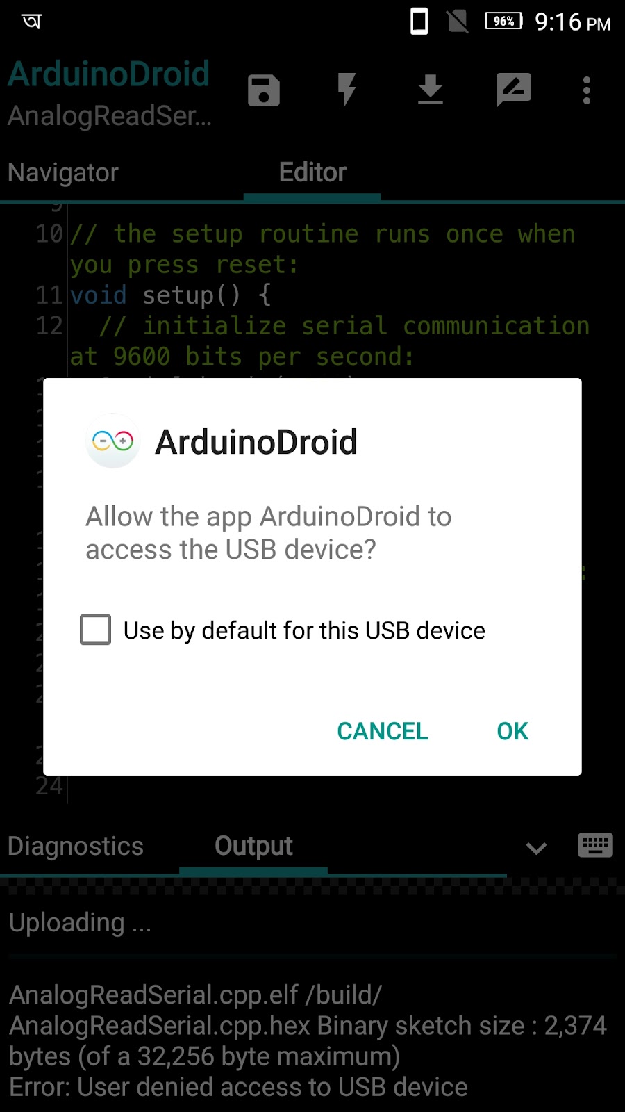
7. Upload the sketch: Click on the upload icon from the toolbar in the app. Upload should start once you get a pop-up dialog like this:
Figure 3: Arduino board detected successfully
Once you click Okay, the upload shall start and if your code is correct and matches the particular Arduino circuit board, you shall get a successful upload, which was not the case earlier for the error : “no Arduino boards found” on clicking the upload button.
So, that’s it then. Hope this blog adds value to your development skills and you can continue working bug free with your Android-Arduino connections.
A Splash Screen is basically a nice intro-screen that mobile applications have on startup of the app on a device. The splash screen can be customized according to the app’s UX need-animations, sound effects, etc. are some common tweaks to a simple splash screen.
I have been working with FOSSASIA on the Neurolab Android App where we made a splash screen for the same. Our implemented splash screen is below:
Neurolab Splash Screen
While developing this, we followed Google Material Design guidelines and the pattern it suggests is termed as ‘Launch Screen’. Displaying a launch screen can decrease the sense of long load time, and has the potential to add delight to the user experience. Launch screen implementation is considered as one of the best-practised development skills for a proper splash screen for an app.
Implementation
Now, it is not a good idea to use a splash screen that wastes a user’s time. This should be strictly avoided. The right way of implementing a splash screen is a little different. In the new approach specify your splash screen’s background as the activity’s theme background. This way, we can effectively and efficiently use the time gap between the startup of the app and the onCreate() method.
In the Neurolab app, we use the splash screen as a bridge for the time gap between the app startup when we click the app icon and the onCreate method of the Neurolab Activity (Main/Launcher Screen) of the app, wherein the various UI components are laid out on the screen and the functionalities, navigations, listeners are linked to those components.
So, here we won’t be creating a new layout for the Splash screen as a separate activity. Rather we would specify the theme of the landing activity as the splash screen.
We create a drawable named splash_screen.xml in our project and give a parent tag of layer-list. Here is the code for our drawable file:
Next, we are going to create a new theme in the styles resource file. This theme is going to be used as the base theme for the main activity screen of the app. In this style, we specify our created drawable file to the property name windowBackground.
Then, update this style in the project manifest file to set the theme of the main activity
android:theme="@style/AppTheme.Launcher"
Having done the steps so far, we create a simple class extending the AppCompatActivity. Note- This may seem like another Activity screen, but it is not. We don’t specify the setContentView() here. Instead of this class just directs to the main/home activity using an Intent. Finally, be sure to finish() the SplashActivity activity (class) to remove prevailing unused/idle activities from back stack.


You must be logged in to post a comment.