
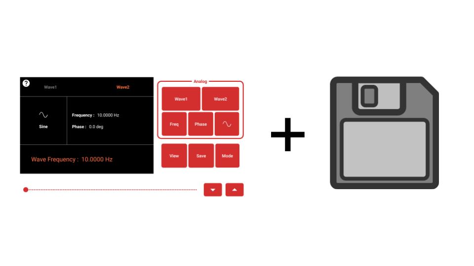
How to use and implement Save Wave Configs feature in Pocket Science Lab Wave Generator
What is a Wave Generator?
A Wave Generator is one of the most important features of PSLab. It is used to generate different kinds of waves like, sine, triangular, square, PWM. Wave generator UI is as under:
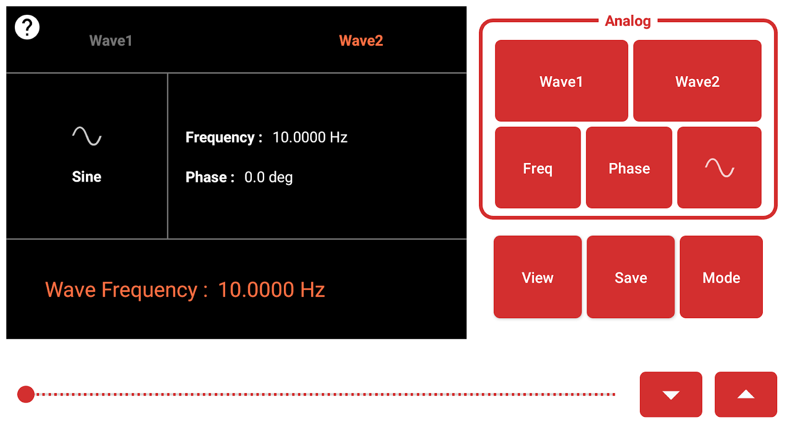
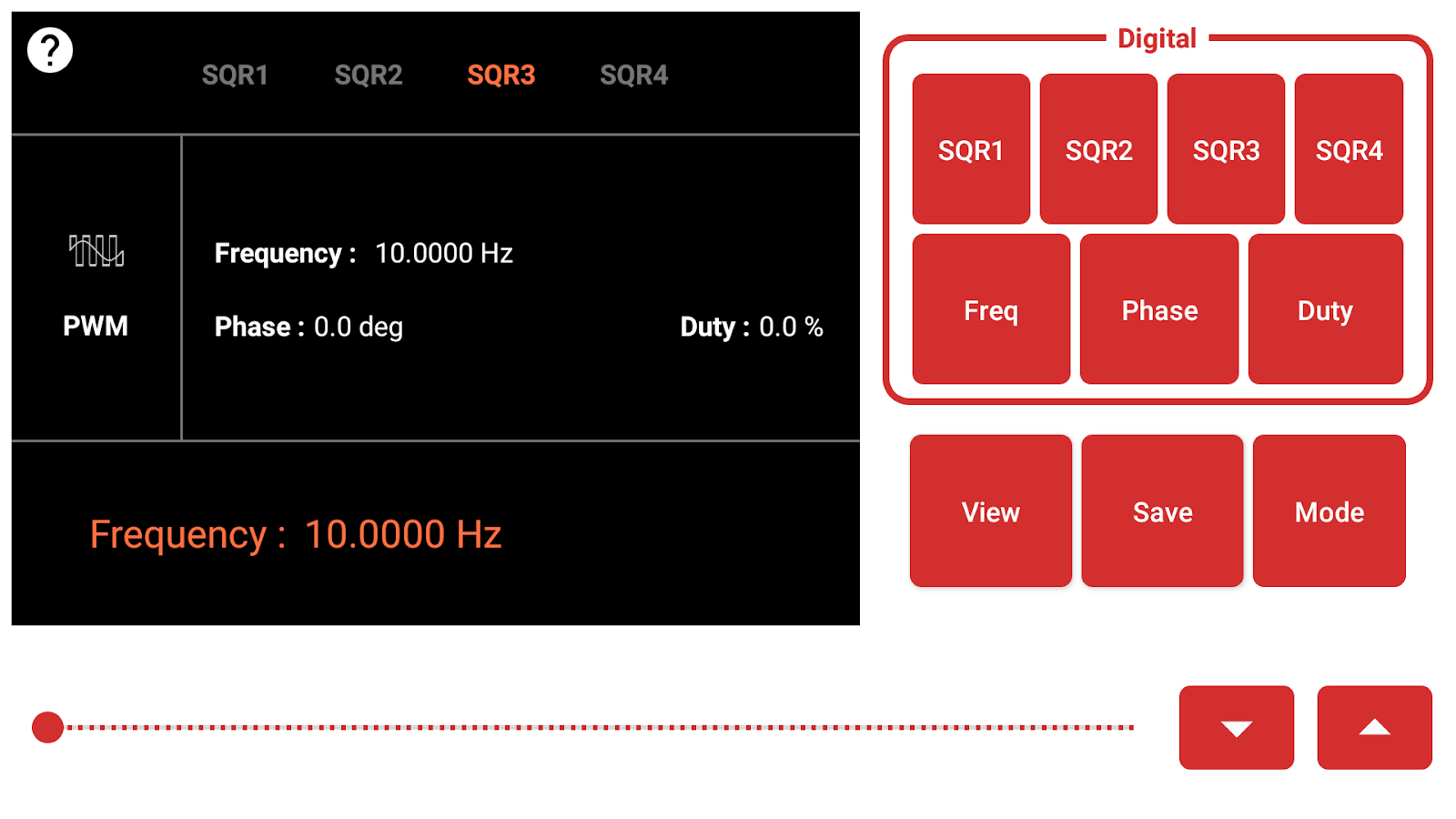
As can be seen the Screenshot above user is provided with options to set Frequency, Phase, Duty of different waves and once configurations are set user can either output the waves in Oscilloscope or can compare different waves in Logic Analyzer.
What is Save Wave Configs Feature?

(Figure 3 : Wave Generator Control Buttons (View,Save,Mode))
In this feature, the user is given a ”Save” button to use this feature.
The reason to add this feature is that, sometimes we need to perform the same experiment multiple times, is such scenarios if we have to set wave configurations everytime, it will become boring and there will be chances of errors. Hence using the save configs feature, user can currently set configurations in the Local Storage and can use it anytime later.
Further since the Wave Configurations are saved on Local Storage as .CSV file, a user can save configs and can share the file with others so others can as well set their device to same configurations. The saved Wave Configurations can be seen in the DataLogger Activity and opening a saved log would take the user to Wave Generator Activity where all the configs will be set as per the saved log.
A sample CSV of the log data can be seen below.

(Figure 4: Wave Configs CSV file)
How is Save Configs Feature Implemented
The implementation of this feature is quite simple. There is a class named WaveData. With the parameters of Mode(Square or PWM), Wave name, Shape, Freq, Phase and Duty. Whenever the user clicks the save configs button, the saveWaveConfigs() function is called. This function fetches set values of different fields and creates realm objects and also write them to csv file as shown above. Once the realm objects are created, this log can be seen in the Data Logger Activity. The code to generate the realm object for the wave configs (that is the implementation of the function saveWaveConfig()) is given below.
public void saveWaveConfig(View view) {
        long block = System.currentTimeMillis();
        csvLogger.prepareLogFile();
          csvLogger.writeMetaData(getResources().getString(R.string.wave_generator));
        long timestamp;
        double lat, lon;
        String data = "Timestamp,DateTime,Mode,Wave,Shape,Freq,Phase,Duty,lat,lon\n";
        recordSensorDataBlockID(new SensorDataBlock(block, getResources().getString(R.string.wave_generator)));
So till now in the function, we create a header string for the data to be stored in the csv file. We create a block from the current system time. This block will be used to save all the realm object for this function, so all the objects created at this instance will be grouped as a single log entry in DataLoggerActivity.
double freq1 = (double) (WaveGeneratorCommon.wave.get(WaveConst.WAVE1).get(WaveConst.FREQUENCY));
double freq2 = (double) WaveGeneratorCommon.wave.get(WaveConst.WAVE2).get(WaveConst.FREQUENCY);
double phase = (double) WaveGeneratorCommon.wave.get(WaveConst.WAVE2).get(WaveConst.PHASE);

String waveType1 = WaveGeneratorCommon.wave.get(WaveConst.WAVE1).get(WaveConst.WAVETYPE) == SIN ? "sine" : "tria";
String waveType2 = WaveGeneratorCommon.wave.get(WaveConst.WAVE2).get(WaveConst.WAVETYPE) == SIN ? "sine" : "tria";

timestamp = System.currentTimeMillis();
String timeData = timestamp + "," + CSVLogger.FILE_NAME_FORMAT.format(new Date(timestamp));
String locationData = lat + "," + lon;
Next, in the function we get currently set Frequency for both analog waves and phase in the variables. We also store the selected wave shape for each of the waves. Since each entry in the csv file is required to have a timestamp and a location stamp,here we create common stamps of both types and will append it to each entry further in the function.
else if (data.getMode().equals(MODE_PWM)) {
                WaveGeneratorCommon.mode_selected = WaveConst.PWM;
                switch (data.getWave()) {
                    case "Sq1":
                        WaveGeneratorCommon.wave.get(WaveConst.SQR1).put(WaveConst.FREQUENCY, Double.valueOf(data.getFreq()).intValue());
                        WaveGeneratorCommon.wave.get(WaveConst.SQR1).put(WaveConst.DUTY, ((Double) (Double.valueOf(data.getDuty()) * 100)).intValue());
                        break;
                }
                enableInitialStatePWM();
            }
        }
Here we check whether the currently selected mode is Analog(Square) or Digital (PWM). Above code snippet is for the SQUARE mode block. We create WaveGeneratorData object for both SI1 and SI2 waves based on the parameters we stored earlier. We also append the data to a string, data. Which we will later use to write the log into a csv file.
else {
   double freqSqr1 = (double) WaveGeneratorCommon.wave.get(WaveConst.SQR1).get(WaveConst.FREQUENCY);
   double dutySqr1 = (double) WaveGeneratorCommon.wave.get(WaveConst.SQR1).get(WaveConst.DUTY) / 100;
   double dutySqr2 = ((double) WaveGeneratorCommon.wave.get(WaveConst.SQR2).get(WaveConst.DUTY)) / 100;
   double phaseSqr2 = (double) WaveGeneratorCommon.wave.get(WaveConst.SQR2).get(WaveConst.PHASE) / 360;
   double dutySqr3 = ((double) WaveGeneratorCommon.wave.get(WaveConst.SQR3).get(WaveConst.DUTY)) / 100;
   double phaseSqr3 = (double) WaveGeneratorCommon.wave.get(WaveConst.SQR3).get(WaveConst.PHASE) / 360;
   double dutySqr4 = ((double) WaveGeneratorCommon.wave.get(WaveConst.SQR4).get(WaveConst.DUTY)) / 100;
   double phaseSqr4 = (double) WaveGeneratorCommon.wave.get(WaveConst.SQR4).get(WaveConst.PHASE) / 360;

 data += timeData + ",PWM,Sq1,PWM," + String.valueOf(freqSqr1) + ",0," + String.valueOf(dutySqr1) + "," + locationData + "\n";

 recordSensorData(new WaveGeneratorData(timestamp, block, "PWM", "Sq1", "PWM", String.valueOf(freqSqr1), "0", String.valueOf(dutySqr1), lat, lon));
}
The above code snippet shows a block of the condition when the selected mode is PWM. Here we store the set values of Freq, Phase and Duty for each SQ1, SQ2, SQ3 and SQ4 waves into variables. Once we store the values we create WaveGeneratorData objects for each of the waves and also append the data to the data string to write to the csv. The code above includes details only for SQ1, but exact same procedure is followed for SQ2, SQ3, and SQ4. One we have all the data appended to the string we call the following function to write the data to csv file.
csvLogger.writeCSVFile(data);
We can see that this function basically stores the current set values of different params into a WaveData object. For each of the waveforms in selected mode (analog/digital), a new instance of WaveData object is created and stored into realm.
When the user opens one of the logs, setReceivedData() function is called in WaveGeneratorActivity. This function iterates on the received realm objects and based on the attributes of each object the data is set in the UI automatically. The implementation of this function is given below,
public void setReceivedData() {
        for (WaveGeneratorData data : recordedWaveData) {
            Log.d("data", data.toString());
            if (data.getMode().equals(MODE_SQUARE)) {
                WaveGeneratorCommon.mode_selected = WaveConst.SQUARE;
                switch (data.getWave()) {
                    case "Wave1":
                        if (data.getShape().equals("sine")) {
                            WaveGeneratorCommon.wave.get(WaveConst.WAVE1).put(WaveConst.WAVETYPE, SIN);
                        } else {
                            WaveGeneratorCommon.wave.get(WaveConst.WAVE1).put(WaveConst.WAVETYPE, TRIANGULAR);
                        }
                        WaveGeneratorCommon.wave.get(WaveConst.WAVE1).put(WaveConst.FREQUENCY, Double.valueOf(data.getFreq()).intValue());
                        break;
                }
                enableInitialState();
            }
This function iterates over the received WaveGeneratorData objects. For each object we check what is the mode of the waveData. The above code snippet is used when the mode is SQUARE. We get the waveType from the object, and since for SQUARE mode there are only 2 types : Wave1 and Wave2, we set the attributes for each wave as we get them from the objects using WaveGeneratorCommon
else if (data.getMode().equals(MODE_PWM)) {
                WaveGeneratorCommon.mode_selected = WaveConst.PWM;
                switch (data.getWave()) {
                    case "Sq1":
                        WaveGeneratorCommon.wave.get(WaveConst.SQR1).put(WaveConst.FREQUENCY, Double.valueOf(data.getFreq()).intValue());
                        WaveGeneratorCommon.wave.get(WaveConst.SQR1).put(WaveConst.DUTY, ((Double) (Double.valueOf(data.getDuty()) * 100)).intValue());
                        break;
                }
                enableInitialStatePWM();
            }
        }
Same as before if the mode of the object is PWM, there will be 4 cases : SQ1, SQ2, SQ3 and SQ4. And depending on the data stored in the received objects.
In a nutshell this features enables to save and reuse wave configuration with ease.
A small video to explain the whole functionality of this feature can be found here.
References
Code Repository
Tags
PSLab, Wave Generator, SaveConfig, Android, GSoC 19


You must be logged in to post a comment.