

Controlling Motors using PSLab Device
PSLab device is capable of building up a complete science lab almost anywhere. While the privilege is mostly taken by high school students and teachers to perform scientific experiments, electronic hobbyists can greatly be influenced from the device. One of the usages is to test and debug sensors and other electronic components before actually using them in their projects. In this blog it will be explained how hobbyist motors are made functional with the use of the PSLab device.
There are four types of motors generally used by hobbyists in their DIY(Do-It-Yourself) projects. They are;
- DC Gear Motor
- DC Brushless Motor
- Servo Motor
- Stepper Motor
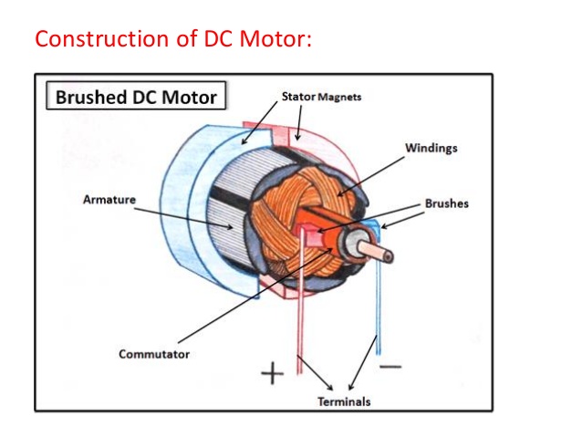
DC motors do not require much of a control as their internal structure is simply a magnet and a shaft which was made rotatable around the magnetic field. The following image from slideshare illustrates the cross section of a motor. These motors require high currents and PSLab device as it is powered from a USB port from a PC or a mobile phone, cannot provide such high current. Hence these type of motors are not recommended to use with the device as there is a very high probability it might burn something.
public void servo4(double angle1, double angle2, double angle3, double angle4)
The experiment supports control of four different servo motors at independant angles. Most of the servos available in the market support only 180 degree rotation where some servos can rotate indefinitely. In such a case, the servo will rotate one cycle and reach its initial position.
scienceLab.stepForward(steps, 100);
scienceLab.stepBackward(steps, 100);
A delay of 100 milliseconds is provided so that there is enough time to produce a step. Otherwise the shaft will not experience enough resultant force to move and will remain in the same position.
These two experiments are possible with PSLab because the amount of current drawn is quite small which can be delivered through a general USB port. It is worth mentioning that as industry grade servo and stepper motors may draw high current as they were built to interact with heavy loads, they are not suitable for this type of experiments.
Resources:
- DC Motor: https://www.slideshare.net/saaz1425/dc-motor-23906628
- Servo Motors: http://www.electronics-tutorials.ws/io/io_7.html
- Stepper Motors: https://en.wikipedia.org/wiki/Stepper_motor
- DIY Projects: http://www.instructables.com/group/diyelectronics

 The figure shows a HC SR04 ultrasound sensor. They are quiet famous in the electronic field; especially among hobbyists in making simple robots and DIY projects. They can be easily configured to measure distance from the sensor up to 400 cm with a measuring angle of 15 degrees. This angular measurement comes into action with the fact that sound travels through a medium in a spherical nature. This sensor will not give accurate measurements when used for scenarios like measuring distance to very thin objects as they reflect sound poorly or there will not be any reflectance at all.
You must be logged in to post a comment.